Copyright 2019, FCA US LLC, All Rights Reserved (tdb)
Revised October 2019
Dealer Service Instructions for:
Customer Satisfaction Notification V54
Engine Cooling Fan
NOTE: Additional steps added to Pages 11 and 15 for (BU) Jeep Renegade
equipped with front tow hooks (sales code XEW).
2015 - 2017 (BU) Jeep
Renegade
2016 - 2017 (FB) FIAT 500X
2015 - 2017 (VM) ProMaster City
NOTE: Some vehicles above may have been identified as not involved in this
campaign and therefore have been excluded from this campaign.
The engine cooling fan on about 192,771 of the above vehicles may experience
excessive friction and loads between motor bushing and shaft due to inadequate
lubrication content in the bushing, out of specification cylindricity and sub-
standard radial strength, leading to bushing wear. This can result in fan motor noise
and eventual failure of the fan motor. Failure of the fan motor can cause the engine
to overheat and possible engine damage/failure due to overheating.
Remedy Available
IMPORTANT: Some of the involved vehicles may be in dealer used vehicle
inventory. Dealers should complete this campaign service on these vehicles
before retail delivery. Dealers should also perform this campaign on vehicles in
for service. Involved vehicles can be determined by using the VIP inquiry process.
Subject
Customer Satisfaction Notification V54 – Engine Cooling Fan Page 2
Inspect and if necessary replace the engine cooling fan module.
Part Number Description
68360299AA Fan Module Radiator Cooling
No parts return required for this campaign. Render the old fan module unusable
and discard.
The following special tools is/are required to perform this repair:
NPN wiTECH micro pod II
NPN Laptop Computer
NPN wiTECH Software
Repair
Parts Information
Parts Return
Special Tools
Customer Satisfaction Notification V54 – Engine Cooling Fan Page 3
1. Open the hood and support it on the prop-rod.
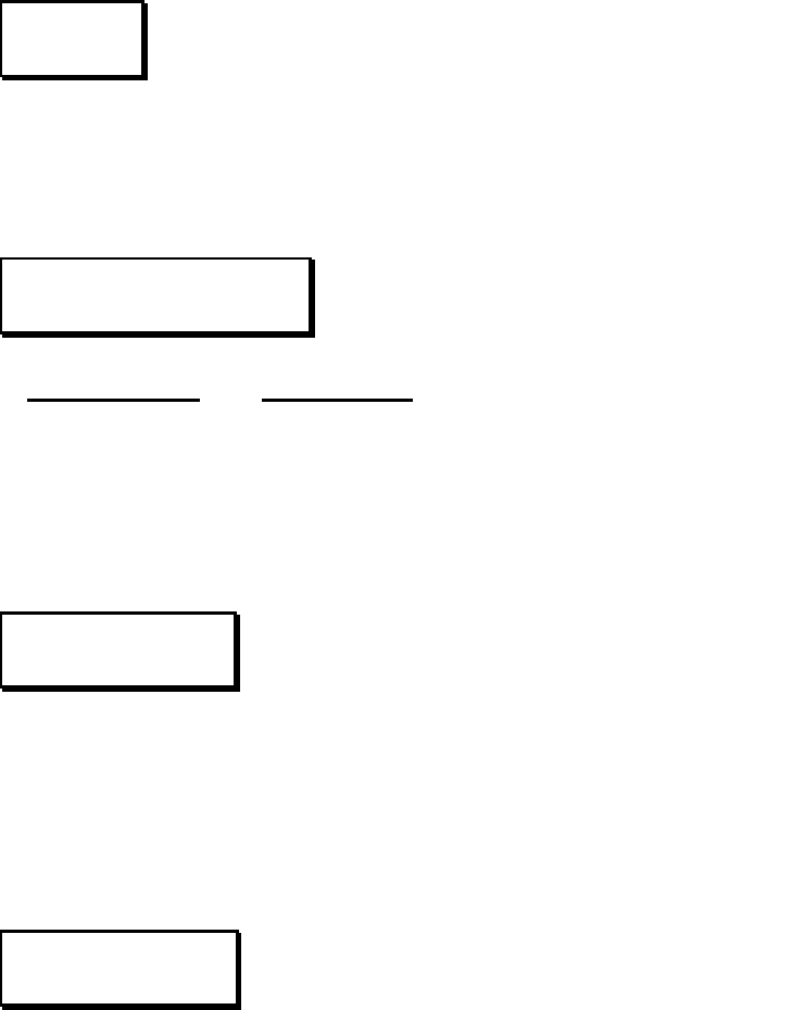
2. Inspect the engine cooling fan motor cover to identify which type of fan is
installed in the vehicle (Figure 1).
If version 1 or 2 is present on the vehicle, replace the engine cooling fan
module. Continue with the Repair Procedure.
If version 3 or 4 is present on the vehicle, no further action is required. Close
the hood and claim the inspection LOP to close this campaign.
Service Procedure
Version 1 – Bushing Version 2 - Bushing
Version 3 – Ball Bearing Version 4 – Ball Bearing
Figure 1 – Engine Cooling Fan Motor Identification
Metal Heat Shield - Metal Top
Hat in Center of Motor
Plastic Heat
Shield
Metal Heat Shield - Plastic
Circle in Center of Motor
Full Metal Heat Shield
with Small Opening

Customer Satisfaction Notification V54 – Engine Cooling Fan Page 4
3. Position the vehicle on a vehicle lift.
CAUTION: The battery
terminals must only be
disconnected with the ignition
in the STOP/OFF position and
key extracted if applicable.
Never disconnect battery
terminals with the ignition in
the RUN position or with
engine running. Wait at least
one minute after placing the
ignition in the STOP/OFF
position before disconnecting
the battery terminals.
4. If the vehicle is equipped with an
Intelligent Battery Sensor (IBS),
disconnect the IBS connector
first before disconnecting the
negative battery cable (Figure 2).
5. Pushbutton Connector: Press
the pushbutton retainer of the
battery negative terminal cable
connector then disconnect by
lifting the battery cable connector
up from the battery negative
terminal (Figure 2).
6. Lever Connector: Loosen the
clamp by rotating the lever
handle in a counter-clockwise
direction. Disconnect and isolate
the clamp from the battery
negative terminal. (Figure 3).
7. Replace the fan module following the appropriate service procedure steps for
(BU) Jeep Renegade and (FB) FIAT 500X or (VM) ProMaster City.
Service Procedure [Continued]
Figure 2 – Battery Cable Negative
Pushbutton Connector
Figure 3 – Battery Cable Negative
Lever Connector
LEVER CONNECTOR
IBS CONNECTOR
PUSHBUTTON
CONNECTOR
BATTERY NEGATIVE
TERMINAL
BATTERY NEGATIVE
TERMINAL
Customer Satisfaction Notification V54 – Engine Cooling Fan Page 5
Procedure for (BU) Jeep Renegade and (FB) FIAT 500X ONLY:
NOTE: Procedure for (VM) ProMaster City begins on Page 18
1. Raise and support the vehicle.
2. Remove the front tire and wheel assemblies.
3. If equipped: Remove the under body protection belly pan.
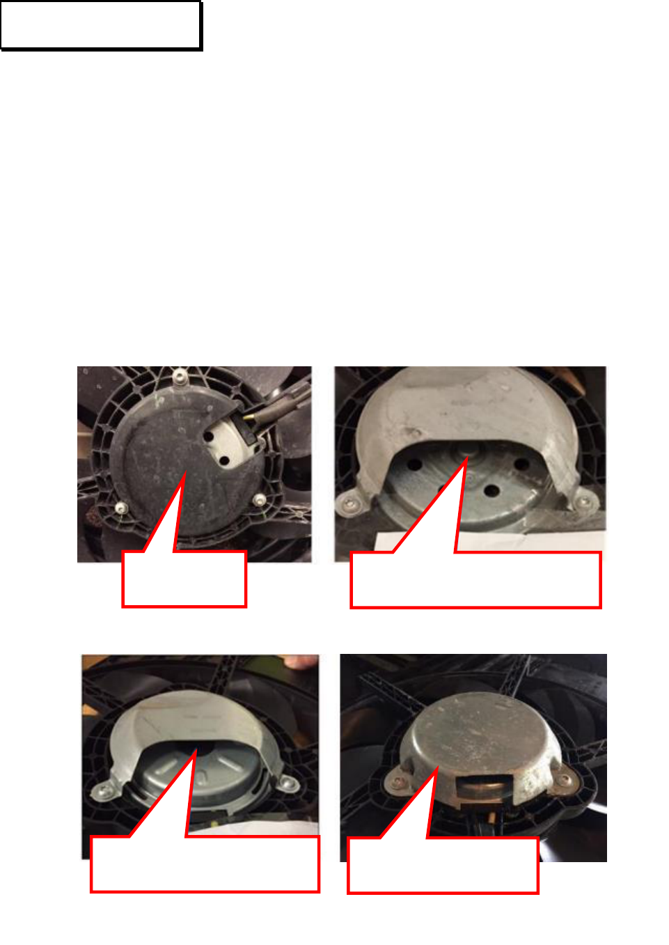
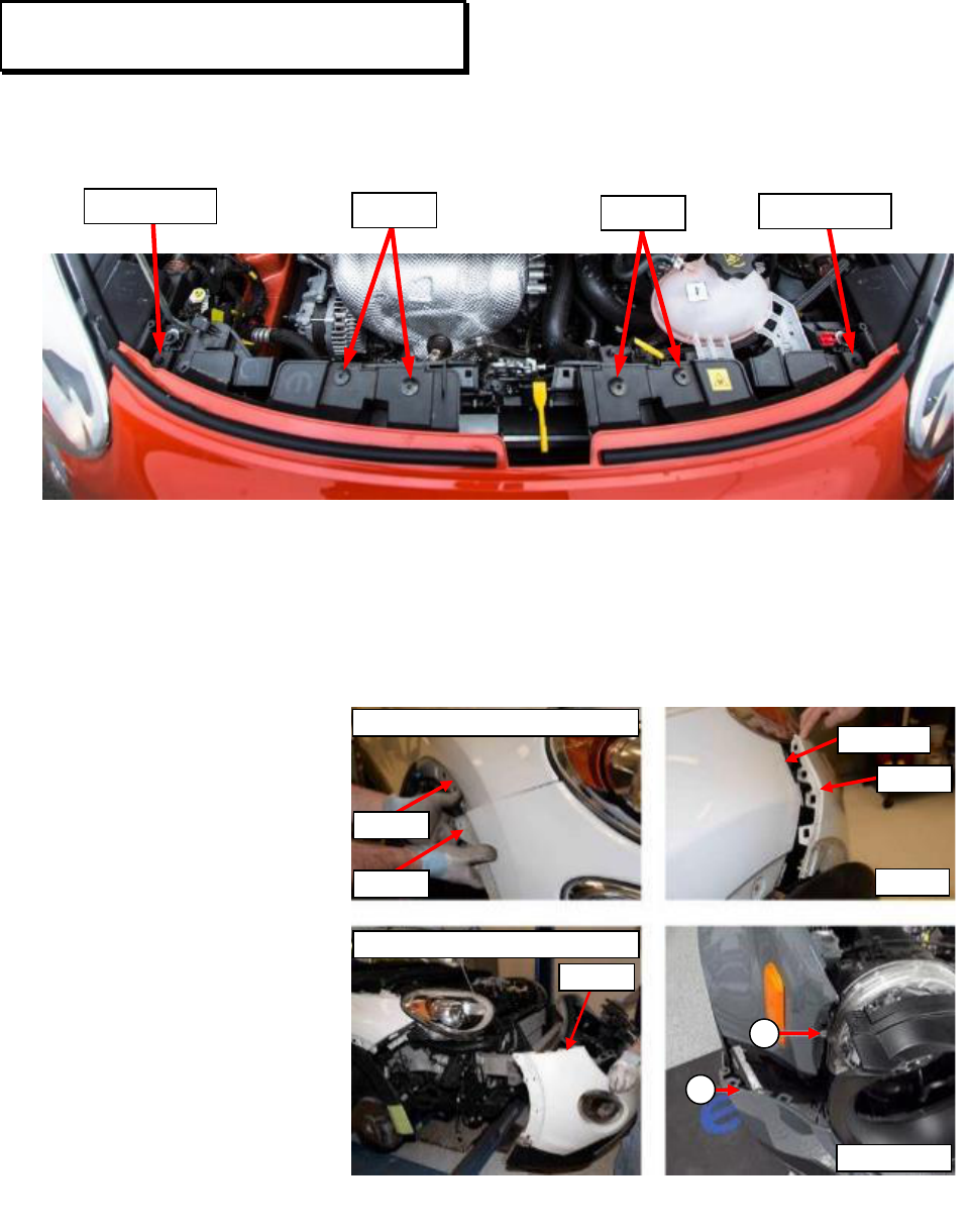
4. Remove the five screws along the lower fascia edge (Figure 4).
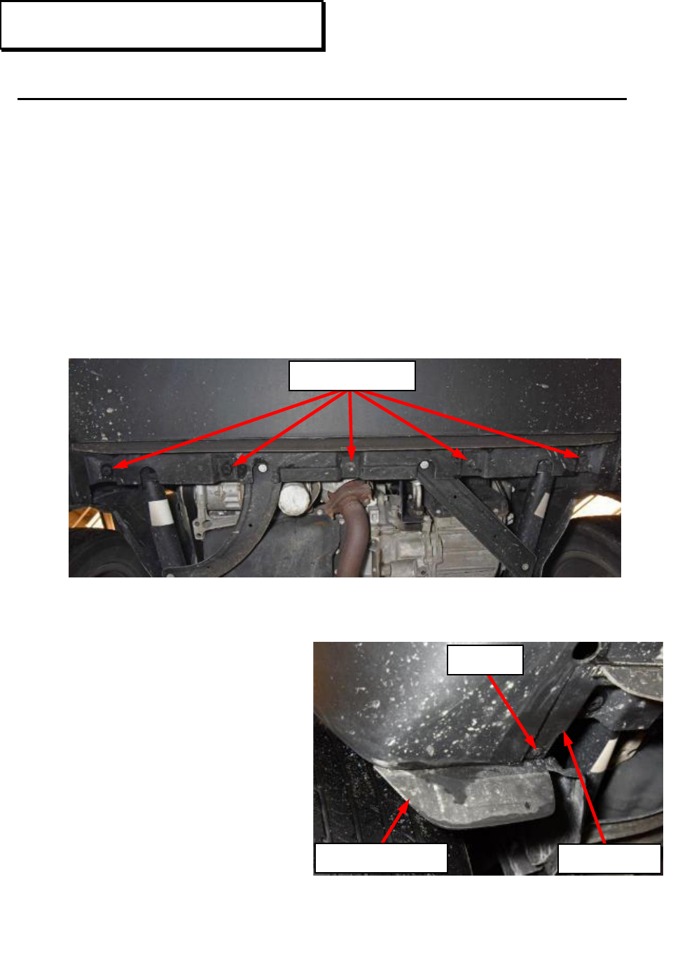
5. Renegade: Remove the screw
on each side attaching the
wheelhouse liner to the front
fascia (Figure 5).
Service Procedure [Continued]
Figure 5 – Wheelhouse Liner to Front
Fascia – Renegade
Right Side Shown, Left Side Similar
Figure 4 – Lower Fascia Screws
SCREWS
SCREW
FRONT FASCIA
WHEELHOUSE LINER
Customer Satisfaction Notification V54 – Engine Cooling Fan Page 6
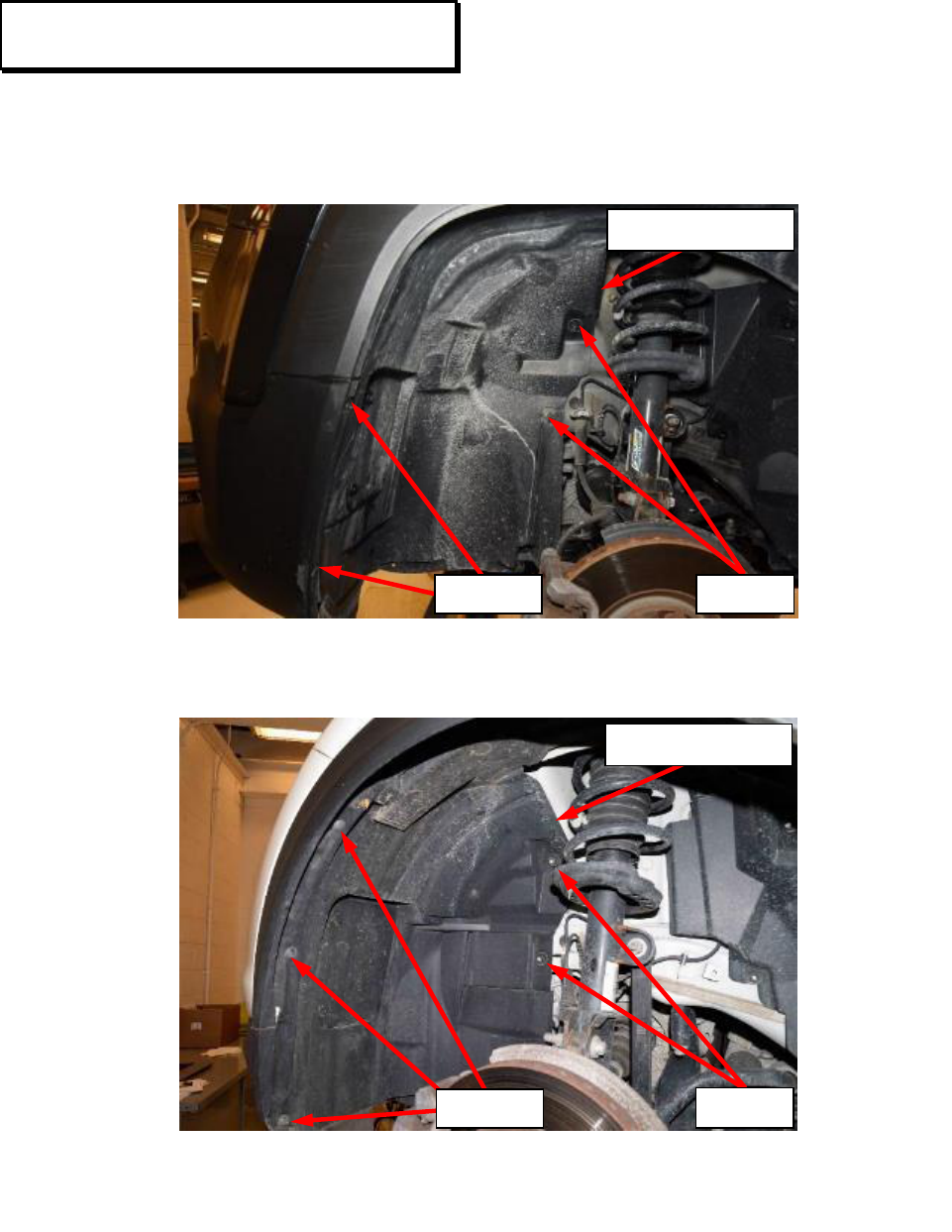
6. Remove the fasteners securing the front half of the front wheelhouse liners on
both sides of the vehicle; Renegade (Figure 6), 500X (Figure 7).
7. Position the front half of the front wheelhouse liners out of the way on both
sides of the vehicle.
Service Procedure [Continued]
Figure 6 – Wheelhouse Liner – Renegade
Left Side Shown, Right Side Similar
Figure 7 – Wheelhouse Liner – 500X
Left Side Shown, Right Side Similar
WHEELHOUSE LINER
SCREWS
NUTS
WHEELHOUSE LINER
NUTS
SCREWS
Customer Satisfaction Notification V54 – Engine Cooling Fan Page 7
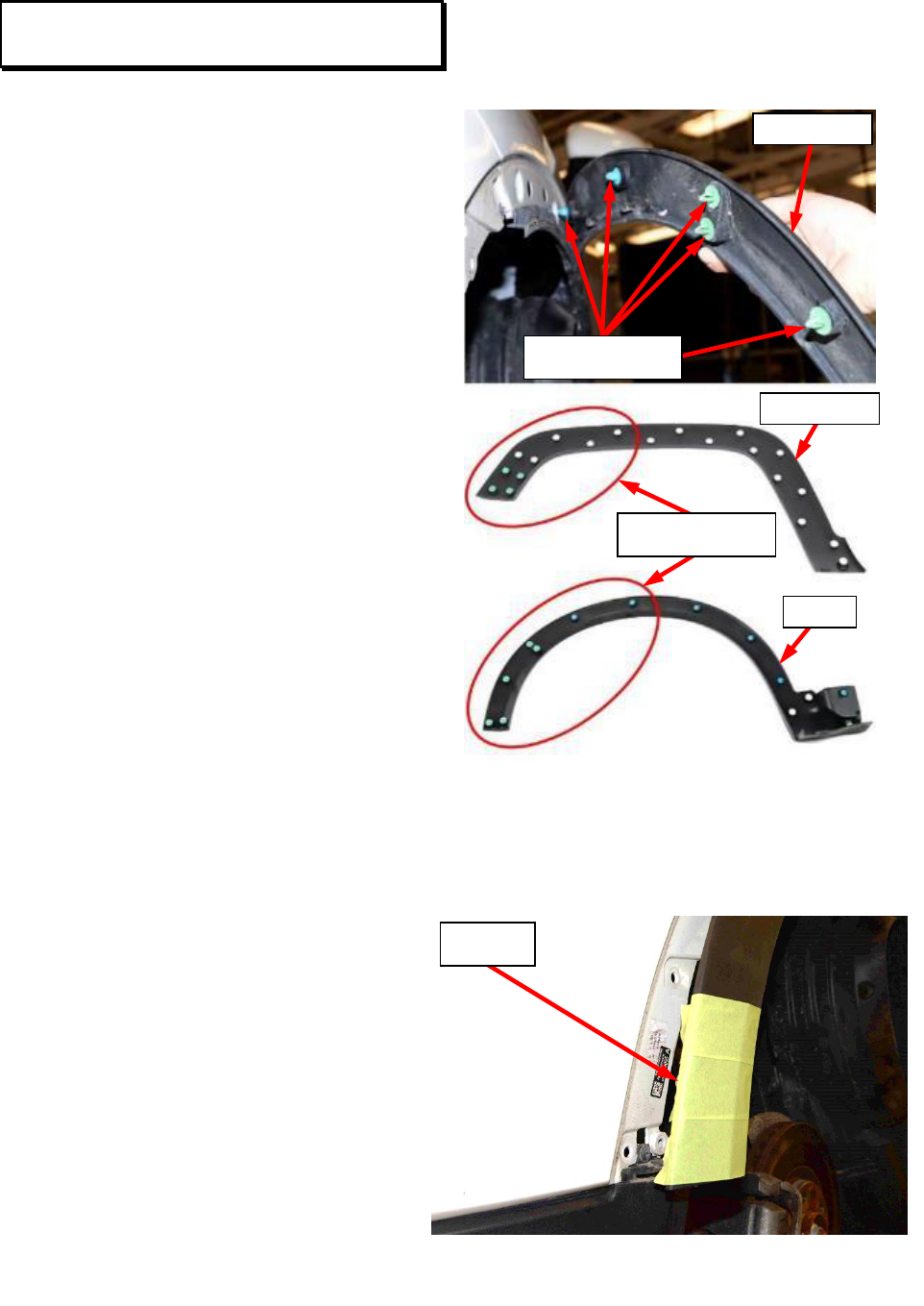
8. Using a small socket or
equivalent to collapse the
retaining clip barbs, release the
retaining clips from inside the
wheel housing. Release only
the front half of the wheel
moldings on both sides of the
vehicle (Figure 8).
9. Install tape on front portion of
wheel moldings to prevent
damage to the wheel moldings
during fascia installation
during vehicle reassembly
(Figure 9).
Service Procedure [Continued]
Figure 8 – Wheel Moldings
Figure 9 – Protective Tape
TAPE
FRONT HALF
RETAINING CLIPS
RETAINING CLIPS
MOLDING
RENEGADE
500X
Customer Satisfaction Notification V54 – Engine Cooling Fan Page 8
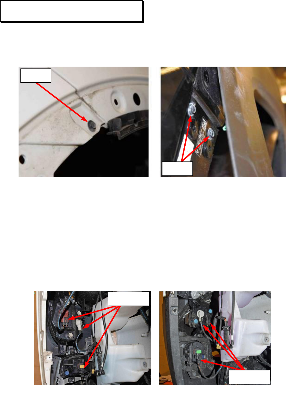
10. Remove the front fascia retaining screws from behind the wheel molding on
each side of the vehicle (Figure 10).
11. 500X: Disconnect the wire harness connectors from the head lamps and fog
lamps if equipped (Figure 11).
12. Renegade: Disconnect the wire harness connectors from the turn signal lamps,
cornering lamps, and fog lamps if equipped (Figure 11).
Service Procedure [Continued]
500X - One Screw Each Side Renegade – Two Screws Each Side
Figure 10 – Fascia Retaining Screws
500X Renegade
Figure 11 – Lamp Connectors
LAMP
CONNECTORS
SCREW
SCREWS
LAMP
CONNECTORS
Customer Satisfaction Notification V54 – Engine Cooling Fan Page 9
13. Lower the vehicle.
14. Renegade: Remove the screws
securing the hood release
handle to the front fascia
(Figure 12).
15. Renegade: Release the cable
retainer securing the hood
release handle cable to the
front fascia (Figure 12).
16. Renegade: Position the hood release handle aside (Figure 12).
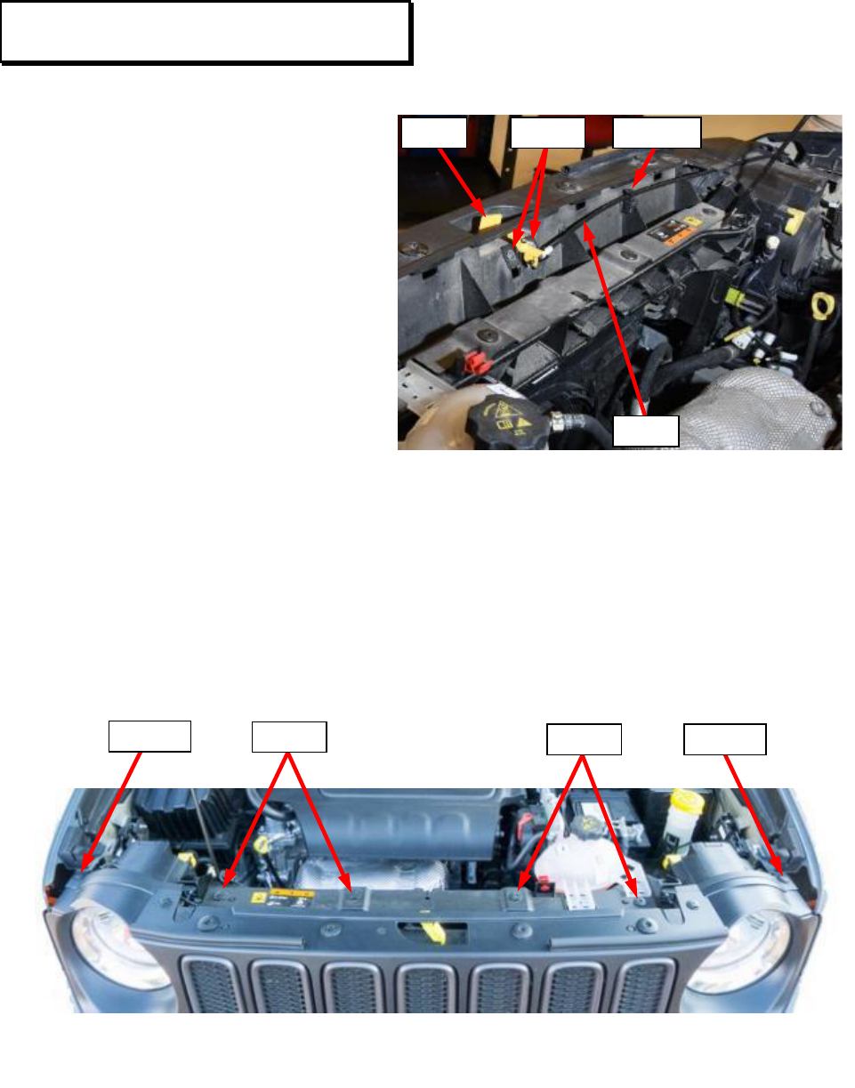
17. Renegade: Remove four fascia screws at the top of the radiator core support
and remove the two outer pushpins (Figure 13).
Service Procedure [Continued]
Figure 12 – Hood Release Handle Screws
SCREWS
LEVER
RETAINER
CABLE
Figure 13 – Front Fascia Fasteners - Renegade
SCREWS
SCREWS
PUSHPIN
PUSHPIN
Customer Satisfaction Notification V54 – Engine Cooling Fan Page 10
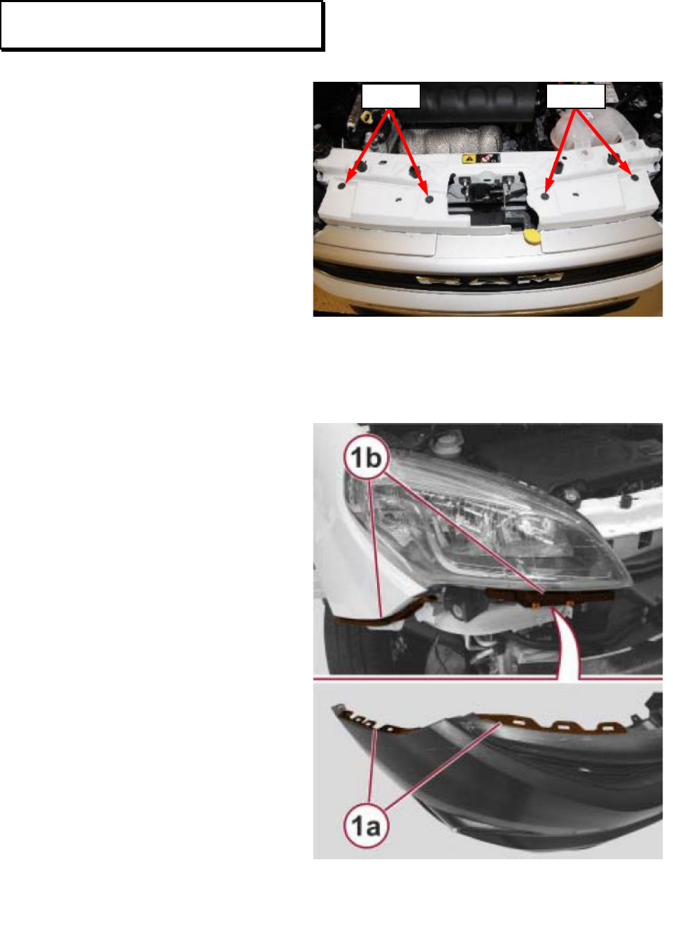
18. 500X: Remove four fascia screws at the top of the radiator core support. Lift
both upper sides of the fascia releasing the retainer pins (Figure 14).
19. 500X: Release the side of the front fascia from the fender bracket. Repeat on
the opposite side (Figure 15).
20. Renegade: Release
the side of the front
fascia (2) from the
fender bracket. Repeat
on the opposite side
(Figure 15).
21. Renegade: With the
use of a plastic pry
tool or equivalent,
release the grill from
the metal clip (1),
securing the grill to
the fender. Repeat on
the opposite side
(Figure 15).
22. Remove the front fascia from the vehicle (Figure 15).
Service Procedure [Continued]
Figure 14 – Front Fascia Fasteners – 500X
RETAINER PIN
SCREWS
SCREWS
RETAINER PIN
Figure 15 – Front Fascia Fasteners
500X
RENEGADE
500X SHOWN RENEGADE SIMILAR
500X SHOWN RENEGADE SIMILAR
1
2
BRACKET
FASCIA
FASCIA
FASCIA
FENDER
Customer Satisfaction Notification V54 – Engine Cooling Fan Page 11
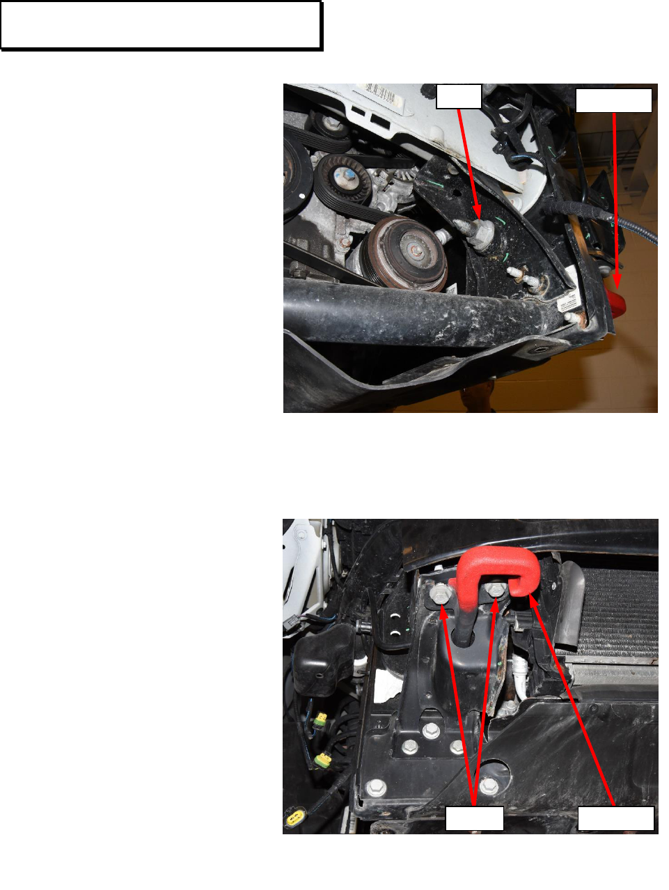
23. Renegade if equipped
with tow hooks: Remove
the nut from the back of the
tow hook (Figure 16).
24. Renegade if equipped
with tow hooks: Remove
the bolts securing the tow
hook to the bumper
reinforcement then remove
the tow hook (Figure 17).
Service Procedure [Continued]
Figure 16 – Front Tow Hooks
Figure 17 – Front Tow Hooks
BOLTS
NUT
TOW HOOK
TOW HOOK
Customer Satisfaction Notification V54 – Engine Cooling Fan Page 12
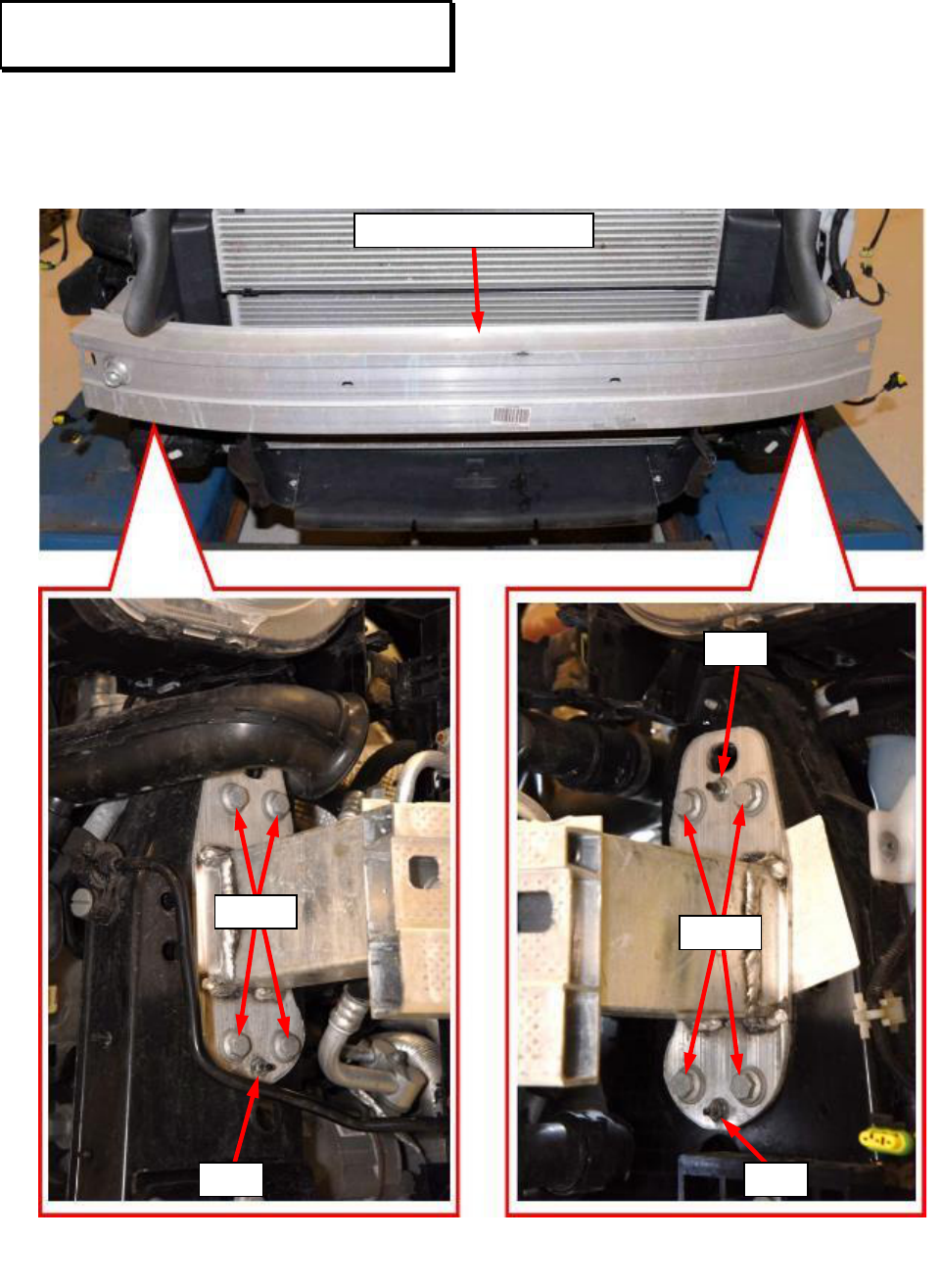
25. Remove the bolts and the nuts then remove the front bumper reinforcement
(Figure 18).
Service Procedure [Continued]
Figure 18 – Front Bumper Reinforcement
BUMPER REINFORCEMENT
BOLTS
BOLTS
NUT
NUT
NUT
Customer Satisfaction Notification V54 – Engine Cooling Fan Page 13
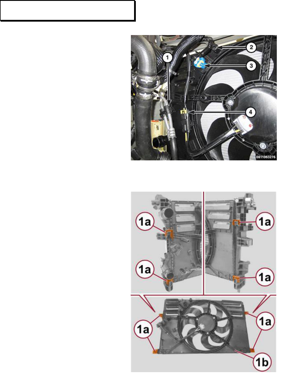
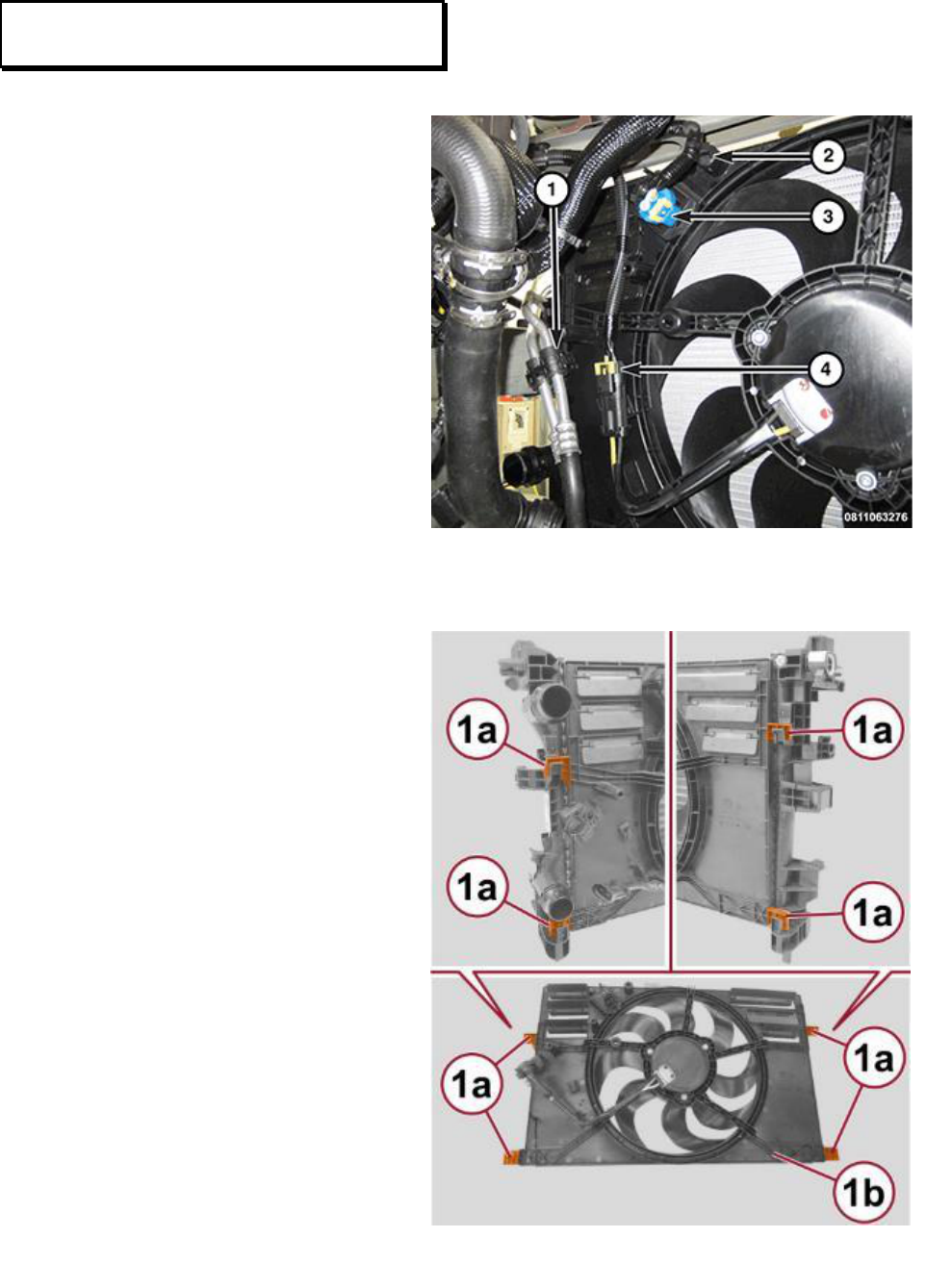
26. Disconnect the resistor wire
harness connector (3)
(Figure 19).
27. Disconnect the cooling fan
wire harness connector (4)
(Figure 19).
28. Detach the wire harness
retainer (2) from fan shroud
(Figure 19).
29. Detach the cooler lines retainer
(1) from the fan shroud
(Figure 19).
30. Release the retaining brackets
(1a) while lifting up on the fan
module (1b) to disengage the
fan module from the radiator
(Figure 20).
Service Procedure [Continued]
Figure 19 – Transmission Cooler
Figure 20 – Transmission Cooler
Customer Satisfaction Notification V54 – Engine Cooling Fan Page 14
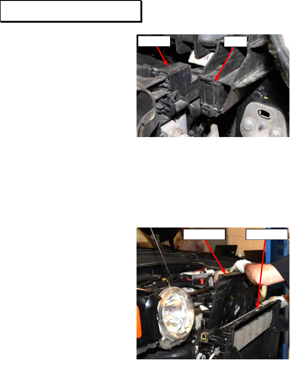
31. Remove the upper radiator
retaining clips on both sides of
the radiator (Figure 21).
32. Tilt the radiator, condenser,
and fan assembly forward for
fan module access (Figure 22).
33. Remove the fan module from
the vehicle (Figure 22). Render
the old fan module unusable
and discard.
NOTE: Be careful to prevent damaging the radiator cooling fins during fan
module removal and installation.
34. Install the new fan module to
the vehicle (Figure 22).
35. Secure the cooling fan (1b)
into the retaining brackets (1a)
(Figure 20).
36. Tilt the radiator, condenser,
and fan assembly rearward into
proper position (Figure 22).
37. Install the upper radiator
retaining clips on both sides of
the radiator (Figure 21).
Service Procedure [Continued]
Figure 21 – Radiator Retainer Clips
500X Shown Renegade Similar
Right Side Shown, Left Side Similar
Figure 22 – Radiator Retainer Clips
Renegade Shown 500X Similar
FAN MODULE
CLIP
RADIATOR
RADIATOR

Customer Satisfaction Notification V54 – Engine Cooling Fan Page 15
38. Attach the cooler lines retainer (1) to the fan shroud (Figure 19).
39. Attach the wire harness retainer (2) to fan shroud (Figure 19).
40. Connect the cooling fan wire harness connector (4) (Figure 19).
41. Connect the resistor wire harness connector (3) (Figure 19).
42. Install the front bumper reinforcement to the vehicle (Figure 18).
43. Loosely install the front bumper reinforcement bolts and the nuts then tighten
the bolts to 40 N·m (30 ft. lbs.) and the nuts to 8 N·m (71 in. lbs.) (Figure 18).
44. Renegade if equipped with tow hooks: Install the tow hook then install the
bolts securing the tow hook to the bumper reinforcement. Tighten the bolts to
40 N·m (30 ft. lbs.) (Figure 17).
45. Renegade if equipped with tow hooks: Install the nut to the back of the tow
hook. Tighten the nut to 23 N·m (17 ft. lbs.) (Figure 16).
46. Position the front fascia to the vehicle (Figure 15).
CAUTION: Be careful of sharp screws on inside of fascia which could
potentially damage the wheel molding during fascia installation. Be sure
wheel molding is protected with tape as directed to do so earlier during the
removal procedure
47. Renegade: Align the grill to the metal clip (1) and insert fully. Repeat on the
opposite side (Figure 15).
48. Renegade: Position the sides of the front fascia (2) to the fender bracket and
insert fully. Repeat on the opposite side (Figure 15).
Service Procedure [Continued]

Customer Satisfaction Notification V54 – Engine Cooling Fan Page 16
49. 500X: Position the side of the front fascia to the fender bracket and insert fully.
Repeat on the opposite side (Figure 15).
50. 500X: Position both upper sides of the fascia onto the retainer pins. Install four
fascia screws at the top of the radiator core support and tighten securely.
(Figure 14).
51. Renegade: Install two outer pushpins securing the fascia to the vehicle
(Figure 13).
52. Renegade: Install four screws securing the fascia to the top of the radiator core
support. Tighten the screws to 20 N·m (15 ft. lbs.) (Figure 13).
53. Renegade: Position the hood release lever and install the screws. Tighten the
screws securely (Figure 12).
54. Renegade: Install the hood release cable and retainer to the front fascia
(Figure 12).
55. Raise the vehicle.
56. Renegade: Connect the wire harness connectors to the turn signal lamps,
cornering lamps, and fog lamps if equipped (Figure 11).
57. 500X: Connect the wire harness connectors to the head lamps and fog lamps if
equipped (Figure 11).
58. Install the front fascia retaining screws behind the wheel molding on each side
of the vehicle. Tighten the screws securely (Figure 10).
59. Remove the protective tape from the wheel moldings.
60. Place the wheel moldings in position and secure the retainers. Repeat on
opposite side of the vehicle (Figure 8).
Service Procedure [Continued]

Customer Satisfaction Notification V54 – Engine Cooling Fan Page 17
61. Install the front wheelhouse liners into their proper position on both sides of the
vehicle.
62. Install the fasteners securing the front wheelhouse liners on both sides of the
vehicle; Renegade (Figure 6), 500X (Figure 7). Tighten the fasteners securely.
63. Renegade: Install the screw on each side attaching the wheelhouse liner to the
front fascia. Tighten the screws securely (Figure 5).
64. Install the five screws along the lower fascia edge. Tighten the screws to
20 N·m (15 ft. lbs.) (Figure 4).
65. If equipped: Install the under body protection belly pan.
66. Install the front tire and wheel assemblies. Tighten the lug nut/bolt to 120 N·m
(89 ft. lbs.)
67. Lower the vehicle.
68. Proceed to: Battery Connection and Fan Function Verification Page 26.
Service Procedure [Continued]
Customer Satisfaction Notification V54 – Engine Cooling Fan Page 18
Procedure for (VM) ProMaster City ONLY:
NOTE: Procedure for (BU) Jeep Renegade and (FB) FIAT 500X begins on
Page 5
1. Raise and support the vehicle.
2. Remove the front tire and wheel assemblies.
3. If equipped: Remove the under body protection belly pan.
4. Remove the four screws along the lower fascia edge (Figure 23).
5. Remove the screws on each side attaching the wheelhouse liner to the front
fascia. Five screws on right side of vehicle, three screws on left side of vehicle
(Figure 23).
Service Procedure [Continued]
Figure 23 – Fascia Fasteners
FRONT FASCIA
WHEELHOUSE LINER
WHEELHOUSE LINER
FIVE SCREWS
THREE SCREWS
FOUR SCREWS
RIGHT SIDE
LEFT SIDE
Customer Satisfaction Notification V54 – Engine Cooling Fan Page 19
NOTE: Right side shown, left
side similar.
6. Remove the fasteners securing
the front half of the front
wheelhouse liners on both
sides of the vehicle
(Figure 24).
7. Position the front half of the
front wheelhouse liners out of
the way on both sides of the
vehicle.
NOTE: Left side shown, right
side similar.
8. Disconnect the wire harness
connectors from the fog lamps
if equipped (Figure 25).
9. Lower the vehicle.
Service Procedure [Continued]
Figure 24 – Wheelhouse Liner
Right Side Shown, Left Side Similar
Figure 25 – Fog Lamp Connectors
Left Side Shown, Right Side Similar
SCREWS RIGHT
SIDE ONLY
SCREWS
NUTS
LAMP
CONNECTOR
Customer Satisfaction Notification V54 – Engine Cooling Fan Page 20
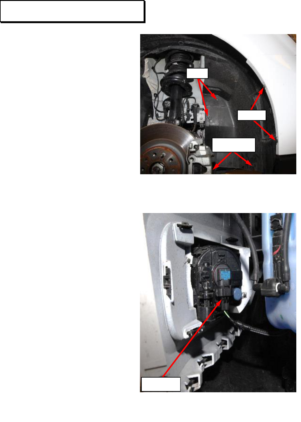
10. Remove the fascia upper
screws at the top of the radiator
core support (Figure 26).
NOTE: Right side shown, left side similar.
11. Release the side of the front
fascia (1a) from the fender
bracket (1b). Repeat on the
opposite side (Figure 27).
12. Remove the front fascia from
the vehicle.
Service Procedure [Continued]
Figure 26 – Front Fascia Screws
Figure 27 – Fascia Fender Brackets
Right Side Shown, Left Side Similar
SCREWS
SCREWS
Customer Satisfaction Notification V54 – Engine Cooling Fan Page 21
13. Disconnect the resistor wire
harness connector (3)
(Figure 28).
14. Disconnect the cooling fan
wire harness connector (4)
(Figure 28).
15. Detach the wire harness
retainer (2) from fan shroud
(Figure 28).
16. Detach the cooler lines retainer
(1) from the fan shroud
(Figure 28).
17. Release the retaining brackets
(1a) while lifting up on the fan
module (1b) to disengage the
fan module from the radiator
(Figure 29).
Service Procedure [Continued]
Figure 28 – Transmission Cooler
Figure 29 – Transmission Cooler
Customer Satisfaction Notification V54 – Engine Cooling Fan Page 22
18. Raise the vehicle.
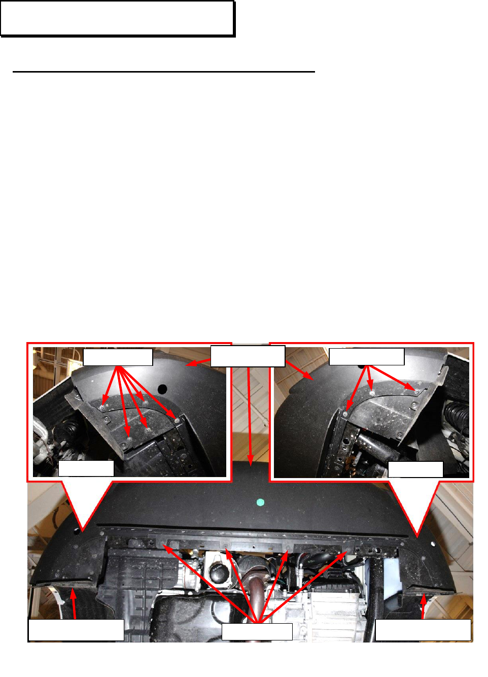
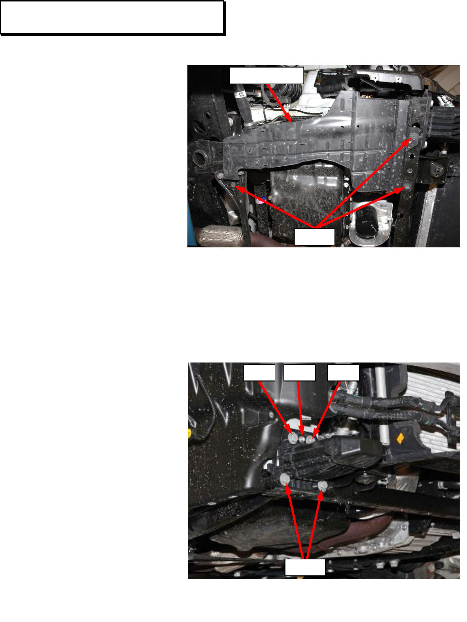
19. Remove the three screws
and the right lower splash
shield. (Figure 30).
NOTE: Right side shown, left side similar.
20. Remove the lower bolts
and loosen the upper
bolts and nut holding the
right and left load beams
to the radiator support.
Do not remove the upper
fasteners (Figure 31).
Service Procedure [Continued]
Figure 30 – Splash Shield
Figure 31 – Load Beam
Left Side Shown, Right Side Similar
SCREWS
SPLASH SHIELD
BOLTS
NUT
BOLT
BOLT
Customer Satisfaction Notification V54 – Engine Cooling Fan Page 23
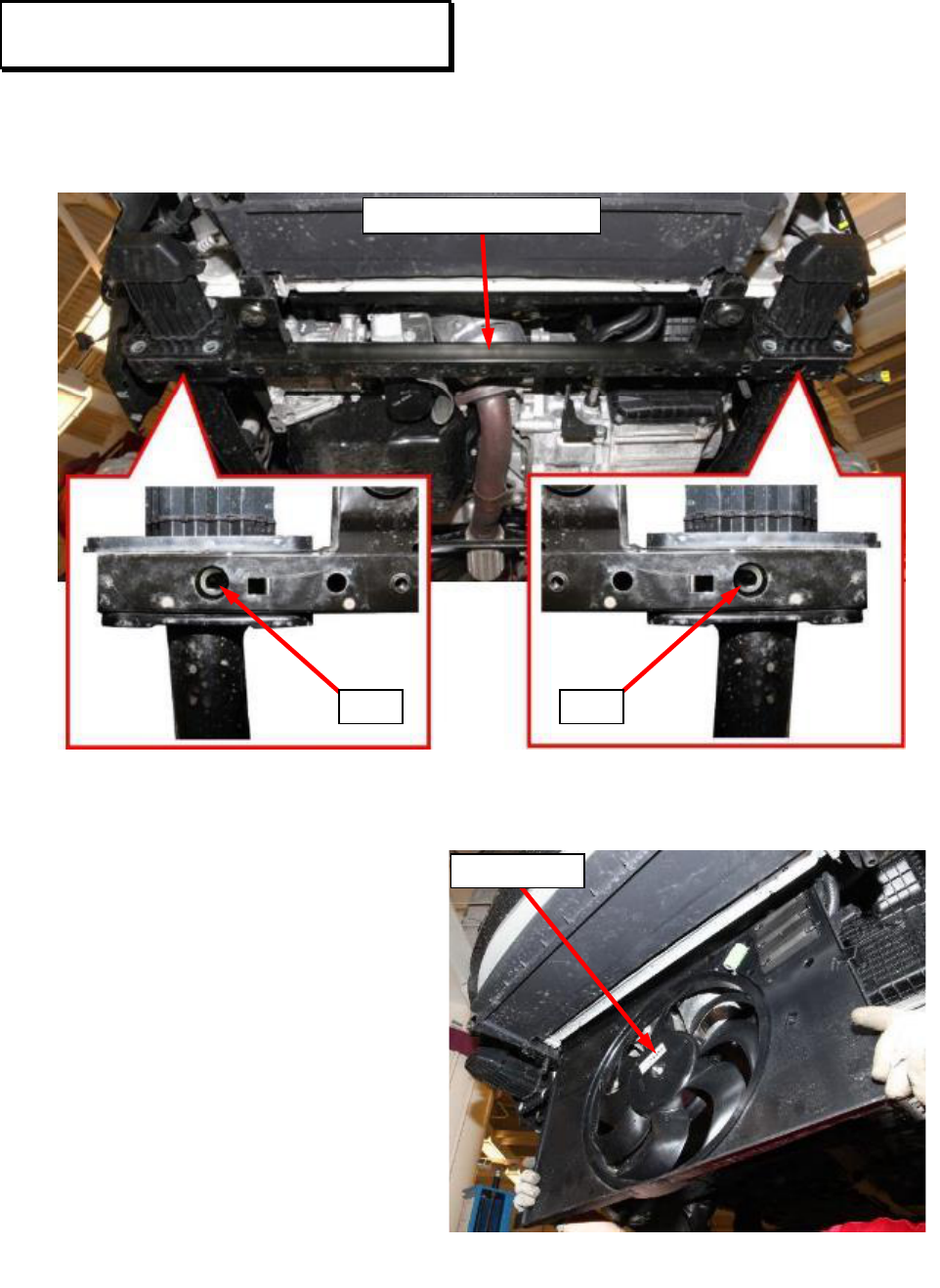
21. Remove the two lower bolts then remove the lower radiator core support
(Figure 32).
22. Remove the cooling fan module
out from the bottom of the
vehicle (Figure 33). Render the
old fan module unusable and
discard.
NOTE: Be careful to prevent
damaging the radiator cooling
fins during fan module
removal and installation.
23. Install the new fan module to
the vehicle (Figure 33).
Service Procedure [Continued]
Figure 32 – Lower Radiator Core Support
Figure 33 – Cooling Fan Module
BOLT
BOLT
RADIATOR CORE SUPPORT
FAN MODULE

Customer Satisfaction Notification V54 – Engine Cooling Fan Page 24
24. Install the lower radiator core support and secure with the two lower bolts. Do
not tighten the bolts at this time (Figure 32).
25. Install the lower bolts securing the right and left load beams to the radiator
support. Tighten the upper and lower fasteners (Figure 31).
Bolts – tighten to 50 N·m (37 ft. lbs.)
Nuts – tighten to 8 N·m (71 in. lbs.)
26. Tighten the lower radiator core support bolts to 27 N·m (20 ft. lbs.) (Figure 32).
27. Install the right lower splash shield and the three screws. Tighten the screws
securely (Figure 30).
28. Lower the vehicle.
29. Secure the cooling fan (1b) into the retaining brackets (1a) (Figure 29).
30. Attach the cooler lines retainer (1) to the fan shroud (Figure 28).
31. Attach the wire harness retainer (2) to fan shroud (Figure 28).
32. Connect the cooling fan wire harness connector (4) (Figure 28).
33. Connect the resistor wire harness connector (3) (Figure 28).
34. Position the front fascia back onto the vehicle.
35. Secure the side of the front fascia (1a) to the fender bracket (1b). Repeat on the
opposite side (Figure 27).
36. Install the fascia upper screws at the top of the radiator core support Tighten the
screws securely (Figure 26).
37. Raise the vehicle.
38. Connect the wire harness connectors to the fog lamps if equipped (Figure 25).
Service Procedure [Continued]

Customer Satisfaction Notification V54 – Engine Cooling Fan Page 25
39. Install the front wheelhouse liners into their proper positon on both sides of the
vehicle.
40. Install the fasteners securing the front wheelhouse liners on both sides of the
vehicle. Tighten the fasteners securely (Figure 24).
41. Install the screws on each side attaching the wheelhouse liner to the front fascia.
Tighten the screws securely (Figure 23).
42. Install the four screws along the lower fascia edge. Tighten the screws securely
(Figure 23).
43. If equipped: Install the under body protection belly pan.
44. Install the front tire and wheel assemblies. Tighten the lug nut/bolt to:
Alloy wheels: 120 N·m (89 ft. lbs.)
Steel wheels: 86 N·m (63 ft. lbs.)
45. Lower the vehicle.
46. Proceed to: Battery Connection and Fan Function Verification Page 26.
Service Procedure [Continued]

Customer Satisfaction Notification V54 – Engine Cooling Fan Page 26
Battery Connection and Fan Function Verification:
1. Connect the battery:
Pushbutton Connector: Install the battery negative cable connector onto
the battery negative terminal (Figure 2).
Lever Connector: Install the battery negative cable clamp to the battery
negative terminal. Tighten the clamp by rotating the lever handle in a
clockwise direction (Figure 3).
2. If the vehicle is equipped with an Intelligent Battery Sensor (IBS), connect the
IBS connector (Figure 2).
3. Install a battery charger and verify that the charging rate provides 13.2 to 13.5
volts. Do not allow the charger to time out during the flash process. Set the
battery charger timer (if so equipped) to continuous charge.
NOTE: Use an accurate stand-alone voltmeter. The battery charger volt
meter may not be sufficiently accurate. If voltage reading is too high,
apply an electrical load by activating the park or headlamps and/or HVAC
blower motor to lower the voltage.
4. Connect the wiTECH MicroPod II to the vehicle Data Link Connector (DLC).
5. Place the ignition in the “RUN” position.
6. Open the wiTECH 2.0 website.
7. Enter your “User id” and “Password” and your “Dealer Code”, then select
“Sign In” at the bottom of the screen. Click “Accept”.
8. From the “Vehicle Selection” screen, select the appropriate vehicle.
Service Procedure [Continued]

Customer Satisfaction Notification V54 – Engine Cooling Fan Page 27
9. From the vehicle “Topology” screen, select the “PCM” icon.
10. From the “PCM” screen select the “Actuators” tab.
11. From the “Actuators” tab select “Radiator/Condenser Cooling Fan Relay #1
Control State” routine and set to “Selected On”. Click “Start” and observe
fan operation to confirm the fan is running then click “Stop” to stop the fan
before exiting the routine. If fan does not operate, additional diagnosis may be
necessary.
12. From the “Actuators” tab select “Radiator/Condenser Cooling Fan Relay #2
Control State” routine and set to “Selected On”. Click “Start” and observe
fan operation to confirm the fan is running then click “Stop” to stop the fan
before exiting the routine. If fan does not operate, additional diagnosis may be
necessary.
13. Place the ignition in the “OFF” position the remove the wiTECH MicroPod II
from the vehicle DLC.
14. Remove the battery changer.
15. Stow the hood prop-rod then close the hood.
16. ProMaster City: Set the clock within the Uconnect radio/information center:
a. Press the “Settings” button on the faceplate to display the menu.
b. Select “Clock & Date” from the settings menu.
c. Set the “date” and “time” or select “Sync Time” if available.
d. Exit the “Settings” menu.
17. Complete the Proof of Correction form for California residents.
18. Return the vehicle to customer or vehicle inventory.
Service Procedure [Continued]

Customer Satisfaction Notification V54 – Engine Cooling Fan Page 28
This campaign is subject to the State of California Registration
Renewal/Emissions Recall Enforcement Program. Complete a Vehicle
Emission Recall Proof of Correction Form (Form No. 81-016-1053) and supply it
to vehicle owners residing in the state of California for proof that this campaign
has been performed when they renew the vehicle registration.
Process Steps to obtain the California Proof of Correction form:
a. Access the “DealerCONNECT” website.
b. Select the “Service” tab.
c. Under the “Publications” heading, select the “ePublishing” link.
d. Sign in using your Dealer Code and Password.
e. Select the “Proof of Correction form”.
Complete Proof of Correction Form for California Residents
Customer Satisfaction Notification V54 – Engine Cooling Fan Page 29
Claims for vehicles that have been serviced must be submitted on the
DealerCONNECT Claim Entry Screen located on the Service tab. Claims paid
will be used by FCA to record Customer Satisfaction Notification service
completions and provide dealer payments.
Use the following labor operation numbers and time allowances:
Labor Operation Time
Number Allowance
Inspect Fan Module 07-V5-41-81 0.2 hours
Inspect and Replace Fan Module 07-V5-41-82 1.4 hours
(BU / FB Models Only)
Inspect and Replace Fan Module 07-V5-41-83 1.3 hours
(VM Models Only)
Optional Equipment
Tow Hook Equipped (sales code XEW) 07-V5-41-60 0.2 hours
(BU Only)
Add the cost of the parts package plus applicable dealer allowance to your claim.
NOTE: See the Warranty Administration Manual, Recall Claim Processing
Section, for complete claim processing instructions.
To view this notification on DealerCONNECT, select “Global Recall System” on
the Service tab, then click on the description of this notification.
Completion Reporting and Reimbursement
Dealer Notification
Customer Satisfaction Notification V54 – Engine Cooling Fan Page 30
All involved vehicle owners known to FCA are being notified of the service
requirement by mail. They are requested to schedule appointments for this service
with their dealers. A generic copy of the owner letter is attached.
All involved vehicles have been entered into the DealerCONNECT Global Recall
System (GRS) and Vehicle Information Plus (VIP) for dealer inquiry as needed.
GRS provides involved dealers with an updated VIN list of their incomplete
vehicles. The owner’s name, address and phone number are listed if known.
Completed vehicles are removed from GRS within several days of repair claim
submission.
To use this system, click on the “Service” tab and then click on “Global Recall
System.” Your dealer’s VIN list for each recall displayed can be sorted by: those
vehicles that were unsold at campaign launch, those with a phone number, city, zip
code, or VIN sequence.
Dealers should perform this repair on all unsold vehicles before retail
delivery. Dealers should also use the VIN list to follow up with all owners to
schedule appointments for this repair.
VIN lists may contain confidential, restricted owner name and address information that was
obtained from the Department of Motor Vehicles of various states. Use of this information is
permitted for this notification only and is strictly prohibited from all other use.
If you have any questions or need assistance in completing this action, please
contact your Service and Parts District Manager.
Customer Service / Field Operations
FCA US LLC
Owner Notification and Service Scheduling
Vehicle Lists, Global Recall System, VIP and Dealer Follow Up
Additional Information
This notice applies to your vehicle,
V54
YOUR SCHEDULING OPTIONS
1. RECOMMENDED OPTION
Call your authorized Chrysler /
Dodge / Jeep
®
/ RAM
BusinessLink / Dealership
2. Call the FCA Recall Assistance
Center at 1-800-853-1403. An
agent can confirm part availability
and help schedule an appointment
3. Visit recalls.mopar.com, scan the
QR code below, or download the
Mopar Owner’s Companion App.
Get access to recall notifications, locate
your nearest dealer, and more through
this website or Mopar Owner’s
Companion App. You will be asked to
provide your Vehicle Identification
Number (VIN) to protect and verify
your identity.
DEALERSHIP INSTRUCTIONS
Please reference CSN V54.
CUSTOMER SATISFACTION NOTIFICATION
Engine Cooling Fan
Dear [Name],
At FCA US LLC, we recognize that the success of our business depends on the satisfaction of
our customers. We are constantly monitoring the quality of our products and looking for
opportunities to improve our vehicles even after they are sold. Because your long-term
satisfaction is important to us, we are contacting you on important improvements we would like
to make to your vehicle
[1]
. This will be done at no charge to you.
We are recommending the following improvements be performed on certain [2015 - 2017 model
year (BU) Jeep Renegade and 2015 – 2017 model year (VM) ProMaster City] vehicles.
WHY DOES MY VEHICLE NEED REPAIRS?
The engine cooling fan on your vehicle may experience excessive friction and loads between
motor bushing and shaft due to inadequate lubrication content in the bushing, out of specification
cylindricity and sub-standard radial strength, leading to bushing wear. This can result in fan
motor noise and eventual failure of the fan motor. Failure of the fan motor can cause the engine
to overheat and possible engine damage/failure due to overheating.
HOW DO I RESOLVE THIS CUSTOMER SATISFACTION NOTIFICATION
FCA will repair your vehicle free of charge (parts and labor). To do this, your dealer will inspect
and if necessary replace the engine cooling fan module. The estimated repair time is 1.5 hours.
In addition, your dealer will require your vehicle for proper check-in, preparation, and check-
out during your visit, which may require more time. Your time is important to us, so
we recommend that you schedule a service appointment to minimize your inconvenience. Please
bring this letter with you to your dealership.
VISIT RECALLS.MOPAR.COM/HELP FOR MORE INFORMATION AND
ANSWERS TO FREQUENTLY ASKED QUESTIONS
TO SCHEDULE YOUR FREE REPAIR,
CALL YOUR CHRYSLER, DODGE, JEEP OR RAM DEALER TODAY
CALIFORNIA RESIDENTS
The State of California requires the completion of this emission repair prior to vehicle
registration renewal. Your dealer will provide you with a Vehicle Emission Proof of Correction
Form after the CSN service is performed. Be sure to save this form since the California
Department of Motor Vehicles may require that you supply it as proof that the CSN has been
performed.
In order to ensure your full protection under the emissions warranty provisions, it is
recommended that you have your vehicle serviced as soon as possible. Failure to do so could
be determined as lack of proper maintenance of your vehicle.
WHAT IF I ALREADY PAID TO HAVE THIS REPAIR COMPLETED?
If you have already experienced this specific condition and have paid to have it repaired, you
may visit www.fcarecallreimbursement.com to submit your reimbursement request online.
[2]
Once we receive and verify the required documents, reimbursement will be sent to you within
60 days. If you have had previous repairs performed and/or already received reimbursement,
you may still need to have the repair performed.
We apologize for any inconvenience, but are sincerely concerned about your satisfaction. Thank
you for your attention to this important matter.
Customer Assistance/Field Operations
FCA US LLC
VEHICLE PICTURE
LOGO
[Model Year and Model]
VIN XXXXXXXXXXXXXXXXX
QR Code

[1] If you no longer own this vehicle, please help us update our records. Call the FCA Recall Assistance Center at 1-800-853-1403 to update your information.
[2] You can also mail in your original receipts and proof of payment to the following address for reimbursement consideration: FCA Customer Assistance, P.O. Box 21-
8004, Auburn Hills, MI 48321-8007, Attention: Recall Reimbursement.
Mr. Mrs. Customer
1234 Main Street
Hometown, MI 48371
This notice applies to your vehicle,
V54
YOUR SCHEDULING OPTIONS
1. RECOMMENDED OPTION
Call your authorized FIAT Studio
2. Call the FCA Recall Assistance
Center at 1-800-853-1403. An
agent can confirm part availability
and help schedule an appointment
3. Visit recalls.mopar.com, scan the
QR code below, or download the
Mopar Owner’s Companion App.
Get access to recall notifications, locate
your nearest FIAT Studio, and more
through this website or Mopar Owner’s
Companion App. You will be asked to
provide your Vehicle Identification
Number (VIN) to protect and verify
your identity.
DEALERSHIP INSTRUCTIONS
Please reference CSN V54.
CUSTOMER SATISFACTION NOTIFICATION
Engine Cooling Fan
Dear [Name],
At FCA US LLC, we recognize that the success of our business depends on the satisfaction of
our customers. We are constantly monitoring the quality of our products and looking for
opportunities to improve our vehicles even after they are sold. Because your long-term
satisfaction is important to us, we are contacting you on important improvements we would like
to make to your vehicle
[1]
. This will be done at no charge to you.
We are recommending the following improvements be performed on certain [2016 and 2017
model year (FB) FIAT 500X] vehicles.
WHY DOES MY VEHICLE NEED REPAIRS?
The engine cooling fan on your vehicle may experience excessive friction and loads between
motor bushing and shaft due to inadequate lubrication content in the bushing, out of specification
cylindricity and sub-standard radial strength, leading to bushing wear. This can result in fan
motor noise and eventual failure of the fan motor. Failure of the fan motor can cause the engine
to overheat and possible engine damage/failure due to overheating.
HOW DO I RESOLVE THIS CUSTOMER SATISFACTION NOTIFICATION
FCA will repair your vehicle free of charge (parts and labor). To do this, your FIAT Studio
will inspect and if necessary replace the engine cooling fan module. The estimated repair time
is 1.5 hours. In addition, your FIAT Studio will require your vehicle for proper check-in,
preparation, and check-out during your visit, which require more time. Your time is important
to us, so we recommend that you schedule a service appointment to minimize your
inconvenience. Please bring this letter with you to your FIAT Studio.
TO SCHEDULE YOUR FREE REPAIR CALL
YOUR FIAT STUDIO TODAY
CALIFORNIA RESIDENTS
The State of California requires the completion of this emission repair prior to vehicle
registration renewal. Your FIAT Studio will provide you with a Vehicle Emission Proof of
Correction Form after the CSN service is performed. Be sure to save this form since the
California Department of Motor Vehicles may require that you supply it as proof that the CSN
has been performed.
In order to ensure your full protection under the emissions warranty provisions, it is
recommended that you have your vehicle serviced as soon as possible. Failure to do so could
be determined as lack of proper maintenance of your vehicle.
WHAT IF I ALREADY PAID TO HAVE THIS REPAIR COMPLETED?
If you have already experienced this specific condition and have paid to have it repaired, you
may visit www.fcarecallreimbursement.com to submit your reimbursement request online.
[2]
Once we receive and verify the required documents, reimbursement will be sent to you within
60 days. If you have had previous repairs performed and/or already received reimbursement,
you may still need to have the recall repair performed.
We apologize for any inconvenience, but are sincerely concerned about your satisfaction. Thank
you for your attention to this important matter.
Customer Assistance/Field Operations
FCA US LLC
VEHICLE PICTURE
LOGO
[Model Year and Model]
VIN XXXXXXXXXXXXXXXXX
QR Code

[1] If you no longer own this vehicle, please help us update our records. Call the FCA Recall Assistance Center at 1-800-853-1403 to update your information.
[2] You can also mail in your original receipts and proof of payment to the following address for reimbursement consideration: FCA Customer Assistance, P.O. Box 21-
8004, Auburn Hills, MI 48321-8007, Attention: Recall Reimbursement.
Mr. Mrs. Customer
1234 Main Street
Hometown, MI 48371
