This bulletin is supplied as technical information only and is not an authorization for repair. No part of this publication may be reproduced, stored in a retreival system,
or transmitted, in any form or by any means, electronic, mechanical, photocopying, or otherwise, without written permission of DaimlerChrysler Corporation.
SUBJECT:
Hydraulic Radiator Cooling Fan System Diagnostic Check Chart Aid
MODELS:
2005 - 2006 (WK / WH) Grand Cherokee
2006 (XK / XH) Commander
SPECIAL TOOLS/EQUIPMENT REQUIRED:
CH9401 StarSCAN® Tool
CH9404 StarSCAN® Vehicle Cable
DISCUSSION:
DESCRIPTION
The 5.7L hydraulic cooling fan is integral to the fan shroud and is located between the
radiator and the engine (Fig. 1).
The power steering pump supplies the hydraulic fluid and pressure to rotate the cooling fan
blade, while the electrical part of the fan is controlled by the Front Control Module (FCM).
The hydraulic fan drive (motor) consists of the three major following components:
• Steering flow control valve
• Fan control valve
• Two stage G-rotor hydraulic drive
The hydraulic fan and drive is not serviceable, except for the fan motor solenoid. Therefore
any failure of the fan blade, hydraulic fan drive (except solenoid) or fan shroud requires
replacement of the fan module. Because the fan blade and hydraulic fan drive are matched
and balanced as an assembly and servicing either separately would disrupt this balance.
CAUTION: Do not attempt to service the hydraulic cooling fan or fan drive
separately, they are serviced as an assembly. Failure to do so may cause
severe damage to the hydraulic cooling fan assembly.
NUMBER: 07-002-05
GROUP: Cooling
DATE: June 24, 2005
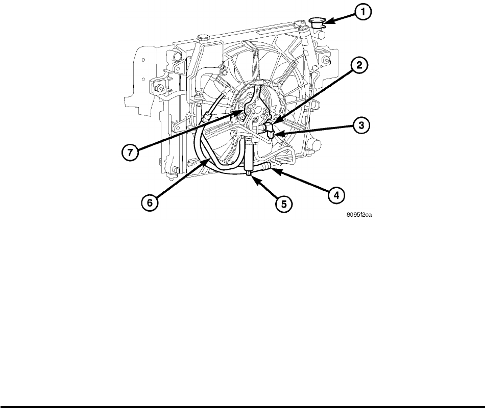
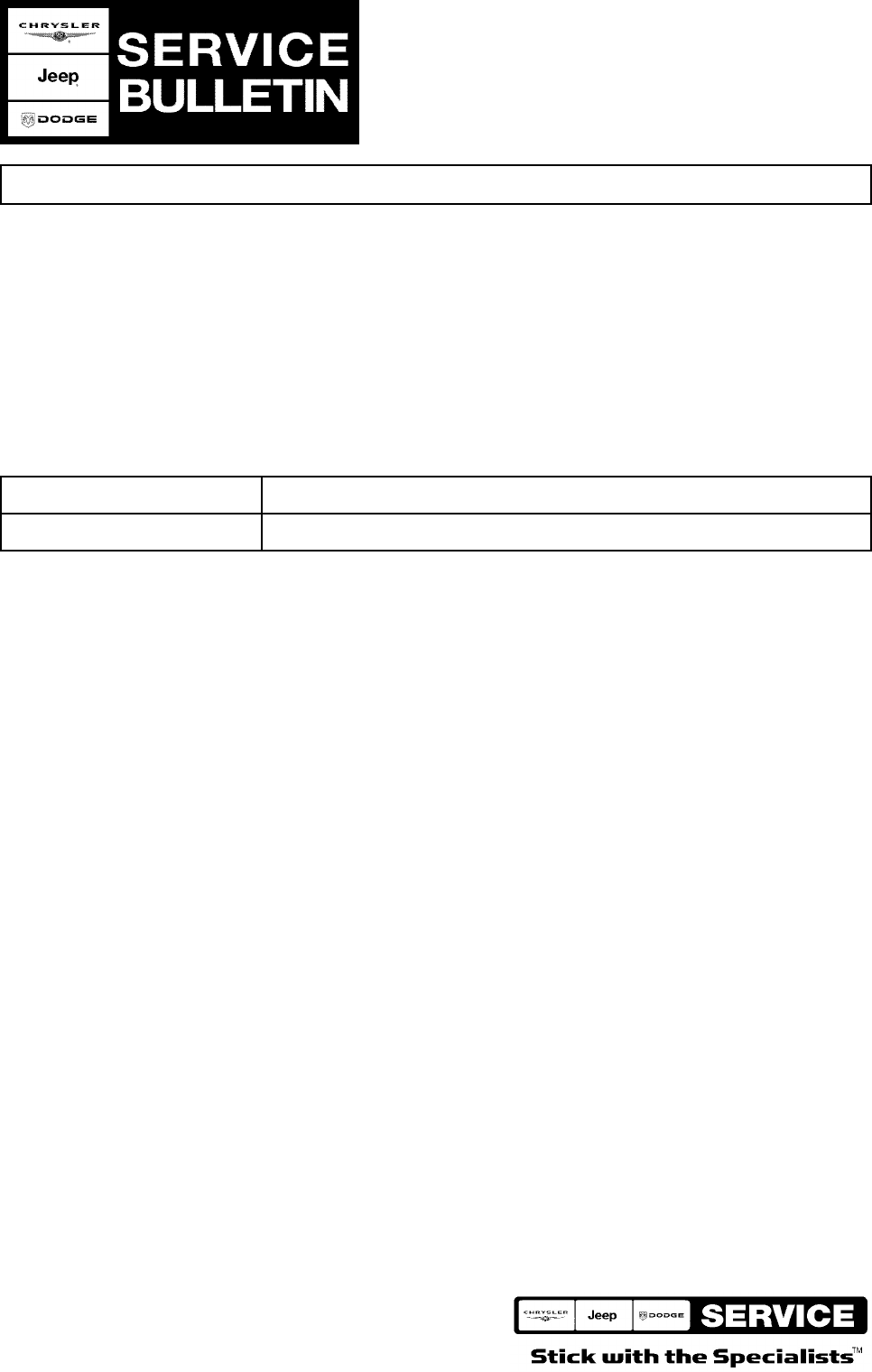
Fig. 1 HYDRAULIC RADIATOR COOLING FAN AND FAN DRIVE - 5.7L
1 - RADIATOR
2 - HYDRAULIC FAN MOTOR SOLENOID
3 - ELECTRICAL CONNECTOR
4 - HIGH PRESSURE LINE INPUT - POWER STEERING PUMP TO HYDRAULIC FAN MOTOR
5 - HIGH PRESSURE LINE OUTPUT - HYDRAULIC FAN MOTOR TO POWER STEERING GEAR (FILTER SHOWN NOT USED /
INSTALLED)
6 - LOW PRESSURE RETURN LINE OUTPUT - HYDRAULIC FAN MOTOR TO POWER STEERING RESERVOIR
7 - HYDRAULIC FAN MOTOR
OPERATION
The hydraulic radiator cooling fan used on the 5.7L gasoline and 3.0L diesel engines
replaces both the electric fan and the engine driven mechanical fan. This provides 5.7L
and 3.0L equipped vehicles with heavy trailer towing capability while at the same time
reducing unnecessary power drain on both the engine and the vehicles electrical system.
HYDRAULIC FAN STRATEGY
The hydraulic radiator cooling fan is controlled by the Front Control Module (FCM). A Pulse
With Modulated (PWM) signal from the FCM controls the fan speed. There are three inputs
to the FCM that determine what percentage of fan speed is required by the vehicle. These
inputs are:
• Engine Coolant Temperature
• Transmission Oil Temperature
• A/C System Pressure
By monitoring the desired operating parameters for these three inputs, the FCM can
determine if cooling airflow is required. If airflow is required, the FCM will slowly speed up
the fan until the parameter(s) are under control. Once the temperature or pressure is
reduced to within operating parameters the fan will speed up, slow down, or hold its speed
to maintain the temperature/pressure requirements.
07-002-05 -2-
NOTE: Even if the FCM is not requesting fan on operation, the fan blade will usually
spin between 100 and 500 RPM when the vehicle is at idle.
ACTIVATING THE HYDRAULIC FAN WITH THE SCAN TOOL (StarSCAN®)
Under the Engine Systems test heading, there is a subheading. “Hydraulic fan solenoid
test”, that has the selections, on/off. Activating the fan with the StarSCAN® will run the fan
at 100% duty cycle, which will help troubleshoot any system problems, and also help with
the hydraulic system deaeration procedure.
NOTE: Engine must be running to activate the fan with the StarSCAN®.
RADIATOR COOLING FAN HYDRAULIC FLUID PATH
Hydraulic fluid is pumped by the power steering pump though a high pressure delivery line
to the fan drive motor. As fluid is diverted through one or both G-rotor stages, rotational
motion is created as fluid moves from the high-pressure (inlet) side of the motor to the
lower-pressure (high pressure outlet) side. Fluid exiting the drive motor is divided into two
paths. In path one, fluid continues through a high pressure delivery line to the vehicle
steering gear to provide steering assist. This fluid then exits the steering gear under low
pressure and travels through a low pressure line to the power steering fluid cooler to be
cooled before being returned back to the power steering fluid reservoir. In path two, excess
fluid travels through a low pressure line back to the power steering pump fluid reservoir
(Fig. 2).
NOTE: There is a steering flow control valve located in the fan drive motor. This
valve operates like the flow control valve found in the typical power steering
pump. A failed pump and/or fan drive can produce contamination that may
cause the steering flow control valve to stick.
-3- 07-002-05
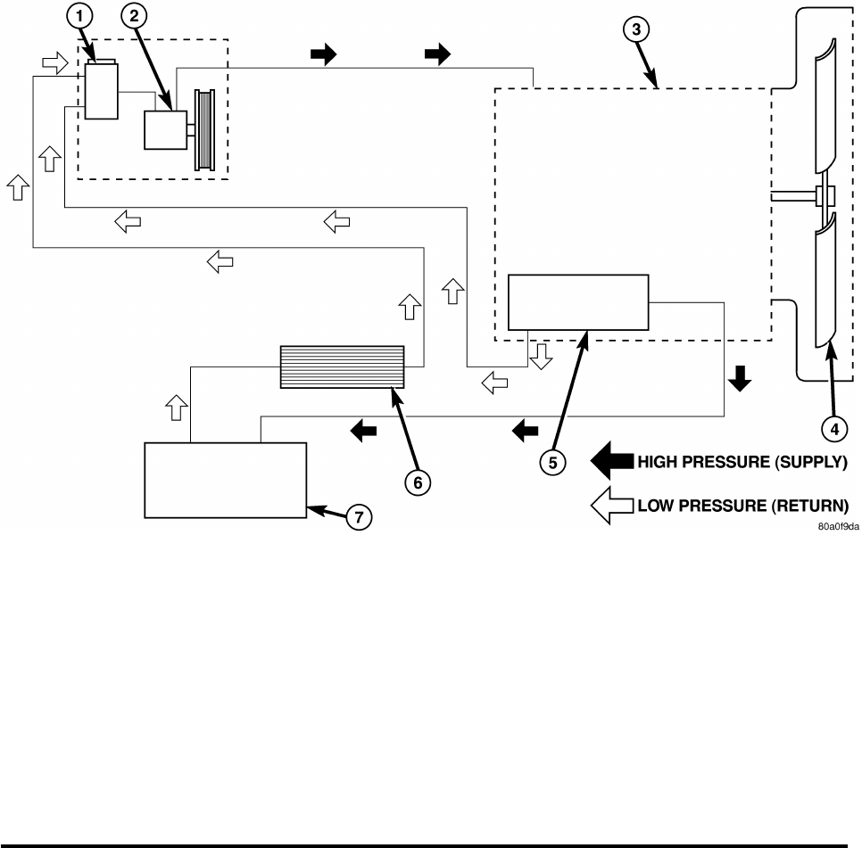
Fig. 2 HYDRAULIC FAN FLUID FLOW CIRCUIT
1 - POWER STEERING RESERVOIR
2 - POWER STEERING PUMP
3 - HYDRAULIC FAN DRIVE ASSEMBLY
4 - FAN BLADE
5 - HYDRAULIC FAN CONTROL SOLENOID
6 - POWER STEERING OIL COOLER
7 - STEERING GEAR
DIAGNOSIS:
This diagnostic procedure should be used if the engine overheats or the A/C compressor
cycles rapidly.
1. Non-hydraulic system - Check for low coolant, faulty thermostat, faulty temperature
sensor, etc. - Is there a Non-hydraulic system problem?
a. Yes >> Repair as necessary.
b. No >> Go to Step #2.
2. Power steering fluid - Check the power steering fluid level in the reservoir - Is the
fluid in the power steering pump reservoir below the dipstick “Add” mark?
a. Yes >> Check for leaks and repair as required. Fill the reservoir to the proper level
and proceed to Step #3.
b. No >> Go to Step #3.
CAUTION: Fan blade and/or shroud may have sharp edges!
07-002-05 -4-
3. Radiator cooling fan - Disconnect and isolate the negative battery cable from the
battery. Rotate the fan counterclockwise (as viewed by the driver) using fingertips on
the outer fan blade. Move the fan through 7 full rotations and notice the drag torque. -
Does the fan spin freely through all 7 rotations with minimal finger exertion?
a. Yes >> Go to Step #6.
b. No >> Go to Step #4.
4. Does the torque needed to spin the fan significantly change as the fan is
rotated?
a. Yes >> Go to Step #18.
b. No >> Go to Step #5
5. Is it difficult to turn the fan or does it require the effort of more than one finger?
a. Yes >> Go to Step #18
b. No >> Go to Step #6
6. Testing the system - Connect the negative battery cable to the battery. Using the
StarSCAN® perform the following tests with the engine running at idle speed. - Does
the fan accelerate when given a 100% duty cycle command?
a. Yes >> Go to Step #7.
b. No >> Go to Step #12.
7. Does the fan decelerate when the duty cycle is changed from 100% to 0%?
a. Yes >> Go to Step #8.
b. No >> Go to Step #18.
8. At 0% duty cycle, turn the steering wheel to full left or right stop for up to 5 seconds (to
stop fan rotation). - Does the fan rotate when the steering wheel is returned to
center at 0% duty cycle?
a. Yes >> Go to Step #9.
b. No >> Go to Step #10.
9. Repeat Step #8, ten times. - Does the fan always resume rotation after the wheel
is returned to center?
a. Yes >> The hydraulic fan motor is OK.
b. No >> Go to Step #10.
10. Turn the A/C system on. The ambient temperature or sun load must be high enough to
cause the A/C compressor to cycle, this will normally be above 15.6° C / 60° F. With
the A/C system operational, the fan speed should increase as the refrigerant pressure
rises. If the A/C system does not operate because of low temperature (below 15.6° C /
60° F) or sun load, use the StarSCAN® to step the fan control motor solenoid duty
cycle to 100%. - Does the fan always start soon after the A/C is turned “On” (or
the duty cycle is set to 100%)?
a. Yes >> Go to Step #11.
b. No >> Go to Step #18.
11. Repeat Step #10, ten times stopping the fan between tests by turning the steering
wheel. Does the fan speed always increases when A/C is turned “On” (100% duty
cycle)?,
a. Yes >> The hydraulic motor is OK.
b. No >> Go to Step #18.
12. Does pump noise increase indicating that the system pressure is increasing?
a. Yes >> Go to Step #18.
b. No >> Go to Step #13.
-5- 07-002-05
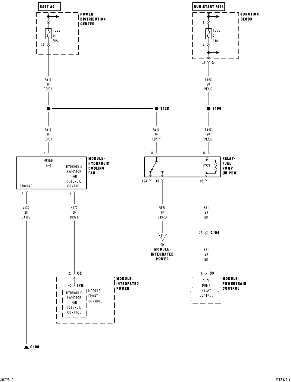
Fig. 3 HYDRAULIC COOLING FAN MODULE CIRCUIT
07-002-05 -6-
13. Electrical testing - Disconnect the 3 pin connector of the fan motor assembly jumper
harness from the vehicle engine compartment wiring harness. Using the connector of
the jumper harness for electrical measurements will normally allow easier access then
if the connector at the hydraulic motor pressure control valve is used. Measure the
resistance between terminal 1 and terminal 2 of the fan motor assembly jumper
harness to determine fan motor solenoid resistance. (Fig. 3) - Is the resistance
between 7 and 13 ohms?
a. Yes >> Go to Step #14.
b. No >> Go to Step #17.
14. Fabricate a 3 wire jumper harness between the vehicle engine compartment wiring
harness and the fan motor assembly jumper harness connector. Insert an ammeter in
the K173 BR/VT circuit (Fig. 3). Start the engine and set the duty cycle to 100%. - Is
the current draw on circuit K173, BR/VT, between 0.5 and 1.5 amps?
a. Yes >> Go to Step #17.
b. No >> Go to Step #15.
15. Inspect for shorted or broken wires. - Were any wires shorted or broken?
a. Yes >> Repair as necessary.
b. No >> Go to Step #16.
16. Replace the Front Control Module (FCM).
17. Replace the fan control motor solenoid and retest the hydraulic fan motor.
18. Replace the hydraulic fan/motor/shroud assembly.
POLICY:
Reimbursable within the provisions of the warranty using diagnostic labor operations for
actual labor time. The Operation Diagnostic labor operations can be located in the 80/90 -
Special Services tab in the Labor Operations Manual. Usage of these operations must
follow the guidelines outlined in the Global Warranty Administration Manual.
-7- 07-002-05
