
DEPARTMENT OF SYSTEMS ENGINEERING
DEPARTMENT OF CIVIL & MECHANICAL ENGINEERING
United States Military Academy
West Point, New York 10996
Guidelines for Technical Communication
Department Guidance
D/SE, D/CME AY 2021
1.01a – 17 August 2020
PREPARED BY
The Faculty
D/SE and D/CME
United States Military Academy
PREPARED FOR
Department Cadets
United States Military Academy
West Point, New York 10996

FOREWORD
The purpose of this guide is to spell out what “right” looks like in technical writing and presenting. As you
compose your papers and presentations in your math, science, and engineering classes, refer to these
pages for advice on communicating like a professional. The audience for this guide is West Point cadets,
and feedback from West Point cadets helped to shape and improve it. The guide’s main body outlines
the fundamental principles of good technical writing and presenting. Because West Point cadets are often
short on time, this main body was kept as short as possible, but it is supplemented by appendices containing
examples and advice on special topics.
This is a living document; feedback is encouraged! If you have ideas for how this guide could be
improved, please send an email to the address below:
Please send feedback to setcf[email protected].
Page | ii
1.01a – 17 August 2020
TABLE OF CONTENTS
Foreword ii
1 Introduction 1
1.1 What is Technical Communication? . . . . . . . . . . . . . . . . . . . . . . . . . . . . . . . . . 1
1.2 Motivation . . . . . . . . . . . . . . . . . . . . . . . . . . . . . . . . . . . . . . . . . . . . . . . 1
1.3 Scope . . . . . . . . . . . . . . . . . . . . . . . . . . . . . . . . . . . . . . . . . . . . . . . . . 1
1.4 West Point Writing Program . . . . . . . . . . . . . . . . . . . . . . . . . . . . . . . . . . . . . 1
1.5 Document Outline . . . . . . . . . . . . . . . . . . . . . . . . . . . . . . . . . . . . . . . . . . 2
2 Models 3
2.1 The Communication Model . . . . . . . . . . . . . . . . . . . . . . . . . . . . . . . . . . . . . 3
2.2 The System Model . . . . . . . . . . . . . . . . . . . . . . . . . . . . . . . . . . . . . . . . . . 4
2.3 The Technical Communication Model . . . . . . . . . . . . . . . . . . . . . . . . . . . . . . . . 4
2.4 Conclusion . . . . . . . . . . . . . . . . . . . . . . . . . . . . . . . . . . . . . . . . . . . . . . 5
3 Basic Principles 6
3.1 Communicate with Purpose . . . . . . . . . . . . . . . . . . . . . . . . . . . . . . . . . . . . . 6
3.2 Use the Right Format . . . . . . . . . . . . . . . . . . . . . . . . . . . . . . . . . . . . . . . . 6
3.3 Omit Needless Words . . . . . . . . . . . . . . . . . . . . . . . . . . . . . . . . . . . . . . . . 6
3.4 Make it Professional . . . . . . . . . . . . . . . . . . . . . . . . . . . . . . . . . . . . . . . . . 6
3.5 Know your Audience . . . . . . . . . . . . . . . . . . . . . . . . . . . . . . . . . . . . . . . . . 7
3.6 Lay a Foundation . . . . . . . . . . . . . . . . . . . . . . . . . . . . . . . . . . . . . . . . . . . 8
3.7 Prepare Well . . . . . . . . . . . . . . . . . . . . . . . . . . . . . . . . . . . . . . . . . . . . . 9
3.8 Proofread and Peer Review . . . . . . . . . . . . . . . . . . . . . . . . . . . . . . . . . . . . . 9
3.9 Pay Attention and Practice . . . . . . . . . . . . . . . . . . . . . . . . . . . . . . . . . . . . . . 9
3.10 Conclusion . . . . . . . . . . . . . . . . . . . . . . . . . . . . . . . . . . . . . . . . . . . . . . 9
4 Technical Writing 10
4.1 Software . . . . . . . . . . . . . . . . . . . . . . . . . . . . . . . . . . . . . . . . . . . . . . . . 10
4.2 Technical Reports . . . . . . . . . . . . . . . . . . . . . . . . . . . . . . . . . . . . . . . . . . 10
4.2.1 More on Introductions . . . . . . . . . . . . . . . . . . . . . . . . . . . . . . . . . . . . 10
4.2.2 The Main Body . . . . . . . . . . . . . . . . . . . . . . . . . . . . . . . . . . . . . . . . 11
4.2.3 Conclusions . . . . . . . . . . . . . . . . . . . . . . . . . . . . . . . . . . . . . . . . . . 12
4.3 Figures and Tables . . . . . . . . . . . . . . . . . . . . . . . . . . . . . . . . . . . . . . . . . . 12
4.4 Equations and Other Technical Matter . . . . . . . . . . . . . . . . . . . . . . . . . . . . . . . 13
4.4.1 Equations . . . . . . . . . . . . . . . . . . . . . . . . . . . . . . . . . . . . . . . . . . . 13
4.4.2 Other Technical Matter . . . . . . . . . . . . . . . . . . . . . . . . . . . . . . . . . . . . 13
4.5 Writing Style . . . . . . . . . . . . . . . . . . . . . . . . . . . . . . . . . . . . . . . . . . . . . 14
4.5.1 Passive and Active Voice . . . . . . . . . . . . . . . . . . . . . . . . . . . . . . . . . . 14
4.5.2 Nominalization and “Zombie Nouns” . . . . . . . . . . . . . . . . . . . . . . . . . . . . 15
4.5.3 First, Second, and Third Person . . . . . . . . . . . . . . . . . . . . . . . . . . . . . . 16
4.5.4 Other Matters of Style . . . . . . . . . . . . . . . . . . . . . . . . . . . . . . . . . . . . 17
4.6 Common Issues . . . . . . . . . . . . . . . . . . . . . . . . . . . . . . . . . . . . . . . . . . . 18
4.6.1 Write Like You Speak, then Clean it Up . . . . . . . . . . . . . . . . . . . . . . . . . . 18
4.6.2 Quantify, Avoid Meaningless Words . . . . . . . . . . . . . . . . . . . . . . . . . . . . 18
4.6.3 When Working in Groups, Integrate . . . . . . . . . . . . . . . . . . . . . . . . . . . . 18
4.6.4 Other Issues . . . . . . . . . . . . . . . . . . . . . . . . . . . . . . . . . . . . . . . . . 18
4.7 Style Guides . . . . . . . . . . . . . . . . . . . . . . . . . . . . . . . . . . . . . . . . . . . . . 19
4.8 Conclusion . . . . . . . . . . . . . . . . . . . . . . . . . . . . . . . . . . . . . . . . . . . . . . 19
1.01a – 17 August 2020
Page | iii
5 Technical Presenting 20
5.1 Good Presenters are Leaders . . . . . . . . . . . . . . . . . . . . . . . . . . . . . . . . . . . . 20
5.2 Slide Rules . . . . . . . . . . . . . . . . . . . . . . . . . . . . . . . . . . . . . . . . . . . . . . 20
5.3 The Parts of a Presentation . . . . . . . . . . . . . . . . . . . . . . . . . . . . . . . . . . . . . 21
5.3.1 Even More on Introductions . . . . . . . . . . . . . . . . . . . . . . . . . . . . . . . . . 21
5.3.2 Main Body . . . . . . . . . . . . . . . . . . . . . . . . . . . . . . . . . . . . . . . . . . 22
5.3.3 Conclusion and Backup Slides . . . . . . . . . . . . . . . . . . . . . . . . . . . . . . . 22
5.3.4 The Three T’s . . . . . . . . . . . . . . . . . . . . . . . . . . . . . . . . . . . . . . . . . 23
5.4 Helping Your Audience . . . . . . . . . . . . . . . . . . . . . . . . . . . . . . . . . . . . . . . . 23
5.4.1 Aesthetics . . . . . . . . . . . . . . . . . . . . . . . . . . . . . . . . . . . . . . . . . . . 23
5.4.2 Figures and Tables . . . . . . . . . . . . . . . . . . . . . . . . . . . . . . . . . . . . . . 23
5.4.3 Ordering and Transitions . . . . . . . . . . . . . . . . . . . . . . . . . . . . . . . . . . . 24
5.4.4 Animation . . . . . . . . . . . . . . . . . . . . . . . . . . . . . . . . . . . . . . . . . . . 24
5.4.5 Bumpers . . . . . . . . . . . . . . . . . . . . . . . . . . . . . . . . . . . . . . . . . . . 24
5.5 Designing for Time . . . . . . . . . . . . . . . . . . . . . . . . . . . . . . . . . . . . . . . . . . 24
5.6 Getting Ready . . . . . . . . . . . . . . . . . . . . . . . . . . . . . . . . . . . . . . . . . . . . 24
5.7 During the Presentation . . . . . . . . . . . . . . . . . . . . . . . . . . . . . . . . . . . . . . . 25
5.8 Common Issues . . . . . . . . . . . . . . . . . . . . . . . . . . . . . . . . . . . . . . . . . . . 27
5.9 Conclusion . . . . . . . . . . . . . . . . . . . . . . . . . . . . . . . . . . . . . . . . . . . . . . 27
6 Assessment 28
7 Conclusion 29
A Supplementary Material 30
A.1 Emails . . . . . . . . . . . . . . . . . . . . . . . . . . . . . . . . . . . . . . . . . . . . . . . . . 30
A.1.1 About Emails . . . . . . . . . . . . . . . . . . . . . . . . . . . . . . . . . . . . . . . . . 30
A.1.2 Parts of an Email . . . . . . . . . . . . . . . . . . . . . . . . . . . . . . . . . . . . . . . 30
A.1.3 Other Email Guidance . . . . . . . . . . . . . . . . . . . . . . . . . . . . . . . . . . . . 31
A.1.4 Example Emails . . . . . . . . . . . . . . . . . . . . . . . . . . . . . . . . . . . . . . . 32
A.2 Abstracts, Executive Summaries, and BLUFs . . . . . . . . . . . . . . . . . . . . . . . . . . . 32
A.3 Quad Charts . . . . . . . . . . . . . . . . . . . . . . . . . . . . . . . . . . . . . . . . . . . . . 34
A.4 Technical Posters . . . . . . . . . . . . . . . . . . . . . . . . . . . . . . . . . . . . . . . . . . . 36
B Examples 38
B.1 Proofing and Refining . . . . . . . . . . . . . . . . . . . . . . . . . . . . . . . . . . . . . . . . 38
B.2 Figures and Tables . . . . . . . . . . . . . . . . . . . . . . . . . . . . . . . . . . . . . . . . . . 39
B.3 Equations . . . . . . . . . . . . . . . . . . . . . . . . . . . . . . . . . . . . . . . . . . . . . . . 44
B.4 Example Theory or Methods Section . . . . . . . . . . . . . . . . . . . . . . . . . . . . . . . . 45
B.5 Department of Defense Distribution Statements . . . . . . . . . . . . . . . . . . . . . . . . . . 47
C Resources 48
D Checklist 50
E Citations 51
F References 53
Page | iv
1.01a – 17 August 2020
Guidelines for Technical Communication
D/SE and D/CME
United States Military Academy
1 INTRODUCTION
Communicating technical information is a critical skill for Army officers. Your ability to inform, explain, clarify,
and persuade will help you to be a good leader and a good team member. One day, your communication
skills could even help save billions of dollars or the lives of others.
Whatever your current communication ability, you can improve. This is as true of a first-semester cadet
as a four-star general. This document is meant to guide you in this process. It is an introduction to basic
principles of good technical writing and presenting. Its intended audience consists of West Point cadets
enrolled in science, math, and engineering courses, although cadets in other departments should also find
the information useful. By the time you have finished reading, you should:
• Understand the basic principles of good technical writing and presenting.
• Be able to use those principles to assess and improve your papers and presentations.
• Understand how your ability to communicate will be assessed in your technical classes.
1.1 What is Technical Communication?
Technical communication is the exchange of technical information, coming from topics such as science,
technology, defense, and medicine. Technical communicators often speak in a “language” of jargon and
other concepts known by members of their specific profession. For an example, think of all the terms,
acronyms, and diagrams unique to the Army that you have been exposed to at West Point. Technical com-
munication includes the papers, presentations, and problem sets that you will work on in your classes. The
term is also used in the professional world to refer to technical manuals or communicating using technol-
ogy,
1
but these are not the focus of this guide.
1.2 Motivation
The way we communicate influences how others think of us and our work. When we communicate poorly,
we frustrate and bore our audience, making it hard for them to take us seriously. But when we write and
present seriously, professionally, and with pride, we encourage and inspire our audience, and they will be
more likely to listen to us and even trust us.
1.3 Scope
The advice in this document is meant to get you started improving your communication, to get you noticing
and practicing new things, and to steer you in the right direction. It is not an exhaustive style guide, a
textbook, or a replacement for a course in technical communication. If you would like to learn more about
technical communication and communication in general, these books are a good place to start:
1. The Elements of Style, by William Strunk Jr. and E.B. White.
2. The Sense of Style, by Steven Pinker.
3. Handbook of Technical Writing, by Gerald J. Alred, Charles T. Brusaw, and Walter E. Oliu.
4. A Guide to Writing as an Engineer, by David F. Beer and David A. McMurrey.
5. Pocket Book of Technical Writing for Engineers and Scientists, by Leo Finkelstein, Jr.
1.4 West Point Writing Program
The West Point Writing Program (WPWP) is another resource for learning about and improving your tech-
nical communication. A primary goal of the WPWP is to help you to develop your writing ability so that you
1.01a – 17 August 2020
Page | 1
Guidelines for Technical Communication
D/SE and D/CME
United States Military Academy
can succeed both at West Point and as an Army officer. Use the WPWP to help you assess and improve
your work. You can find more information about the WPWP in the Resources section (Appendix C).
1.5 Document Outline
This guide consists of a main body followed by appendices, which contain supplemental guidance on spe-
cific topics. In the main body, Section 2 describes three models meant to help you understand the basics
of good communication, which are described in Section 3; Section 4 describes principles of good writing
specifically, while Section 5 does the same for presenting; Section 6 discusses how your communication
will be assessed in your classes; and Section 7 concludes. In the appendix, Appendix A contains supple-
mentary guidance on a myriad of topics, including emails, abstracts, executive summaries, quad charts,
and technical posters; Appendix B contains examples of good technical writing; Appendix C outlines useful
external resources; Appendix D contains checklists to help you complete your assignments; and Appen-
dices E and F contain this guide’s citations and references, respectively.
A final note: to avoid the awkward constructions of gender neutrality—he or she, his or hers, and so
on—a gender was assigned to various hypothetical people in this guide with no intent except for brevity.
Page | 2
1.01a – 17 August 2020
Guidelines for Technical Communication
D/SE and D/CME
United States Military Academy
2 MODELS
Scientists and engineers spend a lot of time using models to think about their work and the world. Below
are three communication-related models that will help you to think about your papers and presentations.
2.1 The Communication Model
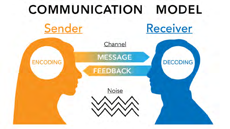
Figure 1: A classic model of two-way communication.
When we communicate, our goal is to share information and understand one another. Say that you want to
communicate something to a friend. First, you have to decide how—you might send a text, use social media,
talk over the phone or in person, or even sketch a picture. Whatever your choice, you have to convert the
information from how it exists in your mind into some message that your friend can sense, usually through
vision or hearing. Crafting the message is often the hardest part of the process, especially when we are
restricted in our method of communication. To experience this yourself, try to explain to someone how to tie
their shoes using words only—no pictures, no demonstrations.
As your friend receives your message, he will try to understand it. Hopefully, you will end up on the
same page, meaning your understanding and your friend’s are close. If they are not, it could be for a variety
of reasons: your words were not clear, Autocorrect mangled your text, your friend could not hear you, or
he did not have some necessary background knowledge. Whatever the outcome, he can tell you how well
he understood you so that you can adjust your message accordingly, although it is often up to the person
sending the message to ask for this feedback.
This process is depicted in Figure 1: a classic model of two-way communication. Although it shows a
conversation between two people, you can extend it to any number of people and any form of communica-
tion.
In this model, you are the sender, who wants to share information with your friend, the receiver. Your
choice of medium—words, a picture, etc.—is called the channel. You convert the information in your head
into a message—a process called encoding—that you communicate along the channel. Anything that
interferes with the message is called noise. Your friend then decodes the message and forms his own
understanding. He might then offer feedback, which is also subject to noise.
Your papers and presentations follow the same process: you are the sender, your audience is the
receiver, and your words and pictures are your message. Communicating well is about creating a message
that is well suited to your audience, adjusting your message based on feedback, and minimizing noise,
which you can think of in two groups:
1.01a – 17 August 2020
Page | 3

Guidelines for Technical Communication
D/SE and D/CME
United States Military Academy
• Physical noise: visual or audio interference like poor lighting, distracting sounds in the room, hard-to-
read text or figures, and, importantly, unnecessary words and pictures in the message.
• Perceptive noise: distractions related to the sender or receiver. For example, while watching a presen-
tation, you might be distracted by a presenter who cannot stand still or by a bad font or color choice.
You might also be distracted for personal reasons, such as a test in your next class or hunger and
tiredness.
2.2 The System Model
Scientists and engineers spend a lot of time thinking about systems. A system is “an integrated set of
elements that accomplishes a defined objective.”
2
Systems are made up of parts (elements) that work
together. Each part serves a purpose, and together the parts serve some greater purpose—the system’s
objective—that they could not achieve on their own. A car, an airplane, and the Army are all systems.
You can adapt the system model to help you create good papers and presentations. Like systems, all
papers and presentations have a purpose and are made up of parts that work together to achieve that
purpose. Each part also serves its own purpose within the greater whole. For example, in a standard five-
paragraph essay, each paragraph is a subsystem of the overall essay, each supports the overall objective
of the essay—to inform and perhaps persuade, and each has its own individual purpose—for example, one
purpose of the introduction is to present a thesis statement.
For systems to work, they must be integrated, meaning their parts must be connected and work together.
The same applies to the parts of your papers and presentations: they should build on each other logically
and transition into one another. Integrating can help you avoid the classic mediocre paper or presentation:
one in which the required components are there (i.e., the “boxes are checked”) but there is no logical flow
between those components. Communicating without logical flow is like piling a bunch of spark plugs, valves,
pistons, and cylinders into a big heap and calling it a working car engine.
Communicating with logical flow means presenting information so that it builds on itself in a way that
makes sense to people who are unfamiliar with that information. This means several things, including
providing background to ensure the audience can understand your work, starting general before getting
specific, explaining how the parts of your work relate to each other as you move through them (known as
transitioning), and only including information that serves a purpose.
2.3 The Technical Communication Model
Technical communication is often used to explain complex and high-stakes topics that are not easy to
understand. Technical communication should be:
• Clear. Good technical communication is direct, accurate, factually correct, and simple. It is not
ambiguous (multiple interpretations), vague (no clear interpretation), or redundant (unnecessary in-
terpretations).
• Concise. Good technical communication contains only the content necessary to get its message
across. It also uses figures and tables to help the audience understand the message with fewer
written or spoken words.
• Precise. Good technical communication uses technical terms correctly. Using the wrong terms con-
fuses and distracts the audience.
• Purposeful. Good technical communication is driven by a purpose involving the audience and the
effect the work is meant to have on them.
• Consistent. Good technical communication uses a single voice and tone and is consistent in the use
of tense, lists, punctuation, captions, and capitalization.
In short, ensure that your assignments are:
CLEAR – CONCISE – PRECISE – PURPOSEFUL – CONSISTENT
Page | 4
1.01a – 17 August 2020
Guidelines for Technical Communication
D/SE and D/CME
United States Military Academy
2.4 Conclusion
As you work on your papers and presentations, keep these models in mind. They will help you to keep
the ultimate purpose of your work in mind: to communicate a well-crafted, cohesive message that your
audience can understand. The advice in the next few sections will help you achieve this.
1.01a – 17 August 2020
Page | 5
Guidelines for Technical Communication
D/SE and D/CME
United States Military Academy
3 BASIC PRINCIPLES
This section outlines nine principles of good communication that apply to both writing and presenting.
Afterwards, Section 4 goes into more detail for writing and Section 5 does the same for presenting.
3.1 Communicate with Purpose
All engineered systems require a purpose. A system’s purpose drives its design and is the basis for judging
its quality. You can improve your papers and presentations by making them purpose driven. For this to
work, make your purposes specific to your content and your audience; attainable, given your constraints
(e.g., time and page limits); relevant to your project and its stakeholders; and impactful to the audience,
meaning your goal should be to affect the audience, not just make information available to them.
For example, say that you need to recommend a course of action (COA) to your senior leadership based
on an analysis that you have run, and you have been given 10 minutes to brief your recommendation. The
purpose of your briefing might be something such as “Brief my senior leadership on the situation requiring
action, the available COAs, and my recommended COA such that they can make an informed decision.” The
impact of this purpose is in the last phrase: such that they can make an informed decision. This element
of the purpose—combined with your knowledge of the audience, your knowledge of the material, and your
time constraints—will drive what gets put into the briefing, what gets left out of it, and how it all fits together.
You can extend this approach to lower levels by considering the purpose of individual sections and
slides. At times, you may want to consider the purpose of individual words to help you decide if you should
keep or delete them.
3.2 Use the Right Format
Format refers to the appearance and high-level contents of your work, including everything from your mar-
gins to your fonts to your slide template to your cover sheet. The right format is important because using
the wrong one can make it hard or impossible for your message to reach its audience. This is because:
• It makes the audience think that you cannot follow directions.
• It makes it harder for the audience to understand your work.
• Publications that call for a specific format will not accept the wrong one.
When a specific format is required in class, you will be informed which one to use. In the Army, formatting
guidelines for many types of documents are described in Army Regulation 25-50 (see Appendix C for a link).
Sometimes, you will be required to use a specific style guide that defines your formatting rules, as described
in Section 4.7.
3.3 Omit Needless Words
In communication, less is more: write or say only what is necessary to fulfill the purpose of your work.
As Strunk & White put it, you should “omit needless words,”
3
but you can extend that principle to omitting
needless figures, tables, and anything else that does not serve a purpose. Writing or saying too much
distracts the audience, gives them more to criticize, dilutes your necessary content, and makes it harder
to edit your work. It is like designing a machine with unnecessary parts: all they do is make the machine
overly complicated, more likely to fail, and harder to fix.
3.4 Make it Professional
Professionals take their jobs seriously. When you apply the same philosophy to your papers and presenta-
tions, then your audience will take you and your message seriously. To be a professional communicator:
• Be consistent in your style to avoid distracting the audience. Consistency is especially important in
group work, where you and your teammates have to combine your contributions into a single product.
Even minor things can distract an audience, such as ending some bullets with periods and others
without.
Page | 6
1.01a – 17 August 2020
Guidelines for Technical Communication
D/SE and D/CME
United States Military Academy
• Be honest about the state of your work. Not knowing everything, having only preliminary results or
an incomplete design, and having unresolved questions are necessary parts of technical work and
should be discussed openly.
• Own your work by understanding and working towards the point of the assignment, not just the
elements of the rubric. If you are not sure what the point of the assignment is, ask your instructor.
• Be on time. To help you meet your deadlines, have a plan to deal with printer and email problems
and other last-minute issues.
• Serve the audience. Make your work pleasing to look at by using high-quality images, clean tables,
an easy-to-read font, and an appropriate template. Also, know your audience and tailor your work to
them. More on knowing your audience in the next section.
3.5 Know your Audience
Imagine that you have been asked to describe what your life is like at West Point. Consider how you might
respond differently to each of these people: your five-year-old nephew, your cousin around the same age
as you, a stranger at the airport, your tactical officer (TAC), a grandparent, your career Navy aunt, a friend
from childhood, a prospective cadet in high school, and the Superintendent.
You would probably give a wide range of responses. Your nephew, for example, has less life experience
than your cousin, and so he will not be able to understand as much, and the prospective cadet in high
school is going to care about different things than your grandparent.
These are elements of knowing your audience. To know your audience means having answers to the
following questions:
1. What does your audience know before seeing your work?
2. What does your audience need to know to understand your work?
3. What is your audience hoping to get out of your work (i.e., what do they care about)?
By tailoring your work to your audience, you will help them to understand it. They will also be grateful
to you for not speaking above or below their understanding. Tailoring your work involves two elements:
content and level. Content refers to what information you communicate, while level refers to the detail and
scope of that content. Thinking back to your two relatives, say that you gave the following answers:
• To your five-year-old nephew: “Being a cadet is hard, but I am learning a lot, and so it’s worth it!”
• To your cousin around the same age: “Being a cadet is hard at times, especially when I get a lot of
work all at once. It reminds me a bit of high school in that way. But I’m learning a lot of valuable
leadership skills that will help as an officer. I’m also looking forward to my capstone project.”
The content of these messages is similar, but you went into more detail with your cousin, explaining more
about why being a cadet is hard and the sorts of things you are learning. You also came to a conclusion
with your nephew—it’s worth it!—whereas you did not with your cousin.
We would call your answer to your nephew high-level and your answer to your cousin low-level. High-
level communication is focused on breadth, conclusions, impacts, take-aways, answering so what?, the
bird’s eye view, and the forest (not the trees). Low-level communication is in the weeds, focusing on depth,
details, processes, rigor, answering how did you figure this out?, the worm’s eye view, and the trees (not
the forest).
Different levels are appropriate for different audiences. For example, an audience of engineers is more
likely to care about the lower-level technical details of your work, whereas an audience of non-technical
decision makers is more likely to care about the higher-level impact of your work on their project goals.
Different levels are also appropriate for different settings. For example, a written report has much more
room for low-level details than, say, a ten-minute presentation. Your choice of level also depends on the
state of your work—the further along it is, the more low-level details you might have to communicate.
1.01a – 17 August 2020
Page | 7

Guidelines for Technical Communication
D/SE and D/CME
United States Military Academy
Explaining a topic at a high level does not make the message incomplete or wrong any more than
viewing your house from an airplane makes the picture less accurate than viewing it from the street. In fact,
explaining at a high level is critical when you are briefing an audience that is either short on time or not as
technically knowledgeable as you.
Sports, with their arcane rules and devoted fans, are a good setting for understanding leveling. Below
are three explanations for baseball’s infield fly rule, each at a different level.
• Low Level: Baseball’s infield fly rule is enacted when there are zero or one outs, runners on first and
second base or the bases are loaded, and the batter hits a fly ball to the infield that, in the umpire’s
estimation, is catchable with ordinary effort. When this situation occurs, the batter is called out and
the runners may advance at their own risk. This rule prevents infielders from automatically acquiring
multiple outs by intentionally dropping the ball and then forcing out two or more runners who, because
of the pop fly, have remained close to their respective bases.
• Medium Level: Baseball’s infield fly rule is meant to prevent an automatic double or triple play when-
ever a catchable pop fly to the infield is hit. It is enacted in circumstances where this could take place
and results in the batter being immediately called out.
• High Level: Baseball’s infield fly rule is enacted under special circumstances to prevent giving an
unfair advantage to the defensive team.
Notice that the high-level explanation is not wrong; it is just less detailed than the other two explanations.
However, for certain audiences, this explanation may be well tailored to what they know and what they want
to know.
3.6 Lay a Foundation
Start your papers and presentations with a clear, strong introduction. Introductions prepare the audience
for the material to come, motivate them to read or listen to it, and give them the background they need to
understand it. They also set the audience’s expectations, helping them to mentally organize your message.
As you might be thinking, creating good introductions is strongly tied to knowing your audience.
Think of an introduction like the foundation of a house. Just as a foundation anchors a house to the
ground below, good introductions anchor your work to what the audience already knows about your subject
area. They do this by providing the background information that your audience might not yet have but
requires to understand and appreciate your work.
∗
Without it, they will have no place upon which to “build”
their understanding.
For example, say that you were briefing a senior Army audience on a new unmanned aerial vehicle
(UAV) that will be used by the Corps of Engineers for surveying bridges and roads. You could be confident
that this audience knows about the Corps of Engineers and its role in the Army (“what the audience already
knows”), but they might not be familiar with the particulars of the surveying missions that the UAV will be
used for and why they are important. For them to understand and appreciate your UAV, you would first
provide background on these missions. This information would also equalize your audience, who might
have different backgrounds and familiarity with your technical area.
Other important components of introductions include:
• The purpose, including what your audience should come away with and potentially what you wish to
learn from your audience (Section 1 is an example).
• The scope, including what your work does and does not address (Section 1.3 is an example).
• An outline of the major sections and their contents (Section 1.5 is an example).
• An early summary of critical takeaways, as in a bottom line up front (BLUF) statement.
∗
In this context, appreciate your work means to understand its importance and implications.
Page | 8
1.01a – 17 August 2020

Guidelines for Technical Communication
D/SE and D/CME
United States Military Academy
3.7 Prepare Well
There is an old saying: “Give me five minutes to chop down a tree, and I will spend the first three sharpening
my axe.” In other words, to do a job well, you must prepare well.
You can prepare well and save time in your papers and presentations by understanding their purpose
and then creating an outline. Outlines do not need to be complex, they can just be a list of the major sections
of your paper or presentation, but you can also expand them to include the purpose and high-level contents
of each section as well as the transitions between them. Using outlines helps you to keep the intended end
state of your work in mind as you are working towards it. Remember the motto of the International Honor
Society for Systems Engineering: “Think about the end before the beginning.”
4
3.8 Proofread and Peer Review
Proofreading means reviewing your work to correct mistakes and refine your words and graphics. Peer
review means having others (i.e., your peers) review your work.
You should proofread not only to correct typos and other obvious errors, but also to refine your message.
However, sometimes you will get so familiar with your own work that you will not be able to tell if it needs
refining or how well others will understand it—a phenomenon called the curse of knowledge.
5
That is the
value of peer review: someone unfamiliar with the work can give you a better sense of how understandable
it will be to your audience.
†
It can be tempting to bypass these steps in an effort to save time, but do not. Remember, it is usually
better to have less to say but to say it well than to have more to say but to say it poorly. Proofread your work
and have it peer reviewed to make sure that you say it well.
3.9 Pay Attention and Practice
No matter your current ability, you can become a better technical communicator. Fortunately, you are
surrounded by others trying to do the same thing. This means you are in the perfect place to pay attention
and practice.
To pay attention means to observe and assess your communication style and those of others, including
your classmates and instructors. For example, when you watch presentations, notice what the presen-
ters do well and what they could do better. Learn from their examples and apply those lessons in your
presentations. Apply the same principles when you are peer reviewing others’ work.
To practice means to present and write often and to mindfully incorporate your lessons learned into each
presentation or paper. As with any skill, the more you practice, the better you will become, but if you practice
well, then you will improve by leaps and bounds instead of by baby steps.
3.10 Conclusion
The principles outlined above are the place to start as you work to improve your papers and presentations.
The next section goes into further detail for creating good papers, while Section 5 does the same for
presentations.
†
As you make revisions, save old versions of your work along the way. Sometimes you will want to reintroduce work that you had
thought you no longer needed.
1.01a – 17 August 2020
Page | 9

Guidelines for Technical Communication
D/SE and D/CME
United States Military Academy
4 TECHNICAL WRITING
Writing will be one of your primary modes of communication as an officer. This section introduces a few
basic concepts that apply to written technical communication, shortened to just papers below.
Papers are a static form of communication; they are completed before the reader sees them and then
can be read at any time and for as much time as the reader likes. This mode of communication is unlike
presentations, which require some real-time improvisation and last a limited amount of time. Because they
are static, papers are well suited to communicating detail, especially low-level detail. Writing also lets you
choose and refine your words carefully, as opposed to improvised speaking. You will encounter many kinds
of written technical communication at West Point: reports, essays, orders, white papers, memoranda, and
even some emails. This section concentrates on technical reports, although the principles outlined below
can be generalized to other types of written communication. You can also find guidance on writing good
emails in Appendix A.
4.1 Software
You will write most of your formal papers using word processing software, for which there are two major
categories:
• WYSIWYG. Pronounced “WIZ-ee-wig,” WYSIWYG stands for “what you see is what you get.” In WYSI-
WYG programs, the appearance of the text on screen closely resembles how it will look printed or
made into a Portable Document Format (PDF) file. Microsoft Word, Google Docs, and Apple’s Pages
are all WYSIWYG software.
• Markup Languages. Markup languages are like coding for documents. The markup language LaTeX
(pronounced “lah-TEK”)
‡
is widely used in technical fields. It is often required for technical reports and
dissertations in the professional world, and it is especially useful for writing math. This document, for
example, was written in LaTeX. R Markdown, which converts analyses created in R into “high-quality
documents, reports, presentations, and dashboards,”
6
is another example. To learn more about LaTeX
and R Markdown, see Appendix C.
Each choice has advantages and disadvantages. LaTeX, for example, is highly configurable and handles
graphics and mathematics well, but it is harder to learn than a WYSIWYG program such as Microsoft Word.
All of these software packages can automate parts of the writing process for you. For example, Mi-
crosoft Word can automatically manage your table of contents, citations, and figure and table captions.
Check the Internet for instructions on how to use these tools. Also, be aware that instructors may require
you to use specific software for some assignments.
4.2 Technical Reports
Technical reports are among the longest and most detailed papers that you will write. They tend to have
several main body sections, a table of contents, an executive summary or abstract, several figures and
tables, and one or more appendices. However, their most important parts are the introduction, main body,
and conclusion, which are the focus of the guidance below. You can find more guidance on abstracts and
executive summaries in Appendix A.
4.2.1 More on Introductions
The importance of good introductions was mentioned back in Section 3.6. Introductions are especially
important in papers, which may contain a lot of low-level detail that cannot be understood without the right
background knowledge. Your audience needs this background knowledge to decode your message, as
described in Section 2.1.
To help your audience appreciate your work, discuss its motivation by introducing your topic and why
it is worth studying. The motivation often includes an extended problem statement, such as the following
made-up paragraph:
‡
Although this pronunciation is common, in reality, there is no one universally accepted pronunciation of LaTeX. However, to avoid
sounding like a newbie, do not pronounce it like the clothing fiber.
Page | 10
1.01a – 17 August 2020
Guidelines for Technical Communication
D/SE and D/CME
United States Military Academy
Flood models are used by insurance companies to determine the likelihood
of catastrophic flooding in a given year. For the Beatnavy River of Upstate
New York, most flood models were created between 1930 and 1945 and do not
take into account recent shifts in flood patterns caused by climate change. As
a result, flood insurance rates in the Beatnavy River Valley no longer reflect ac-
tual probabilities of catastrophic flooding. To prevent costly mismatches between
insurance rates and flood rates, new flood models are required.
Notice that the problem statement introduces a “gap,” or the problem that needs to be solved—in this
case, the mismatch between insurance rates and rates of flooding, which is followed by how the work will
fill that gap—by introducing new flood models.
A background section contains information the reader needs to understand and think critically about
your work. For the example above, the background might include a brief history of flood modeling, a
description of the hydrology of the Beatnavy River Valley, a description of recent changes in flood patterns,
or an introduction to the modeling techniques used in your study.
In your paper’s scope, describe what the paper is and is not about and the topics that it does and does
not cover. Scopes set your readers’ expectations. For the example above, you might state that the work
addresses current changes in flood patterns but does not anticipate future changes: a topic that readers
might reasonably expect to see. It is these sorts of topics that are close to yet outside of a paper’s subject
area that are important to address in the “does not cover” part of the scope. This guide contains a scope in
Section 1.3.
In the outline, you give the reader a road map of your paper, briefly explaining the contents of each
section. This guide contains an outline in Section 1.5.
Finally, literature reviews are surveys of the current state of research for your topic. They serve three
purposes:
7
1. To give your readers relevant background information regarding your research.
2. To demonstrate your familiarity with the research in your field.
3. To show how your work contributes to that field.
Literature reviews are important to both researchers and their audience—for the researchers, literature
reviews help define the unresolved questions in their subject area, and for their audience, literature reviews
help establish the impact and validity of the researchers’ work. At West Point, literature reviews are an
important element of capstone projects. To complete one, first consider the purpose of your work. Then,
find research that relates to yours. For the flood model problem described above, you might identify research
on climate change and the Beatnavy River Valley; however, because establishing new flood models is the
purpose of the work, flood models are where you would concentrate, including their history and current
status. Next, summarize the research, establishing for your audience how it relates to yours and how your
work contributes to the subject area. This last part is key—it is not enough to just list the research and
describe it, you must show how each example is connected to the others and to your own work.
4.2.2 The Main Body
The main body has two goals. The first is to describe the approach that you followed to get your results,
including your methods, processes, experimental setup, models, assumptions, limitations, and constraints.
You should include enough detail so that someone reading your paper could replicate your work.
The second goal is to present the results themselves. Your results might include the outcome of a
simulation or physical experiment; your system’s proposed design; your stakeholder findings, conclusions,
and recommendations; and a myriad of other information. Be sure to discuss this information to help your
reader understand it and its significance.
Cadets are often curious about whether a particular piece of information belongs in the main body or
in an appendix. The following rule of thumb may help: if the information is necessary for the audience to
understand your work or it supports a necessary explanation, it belongs in the main body; if the information
1.01a – 17 August 2020
Page | 11

Guidelines for Technical Communication
D/SE and D/CME
United States Military Academy
may be of interest to some readers but is not necessary, put it in an appendix.
4.2.3 Conclusions
The conclusion is your last interaction with most readers. Use it to summarize the key points and signifi-
cance of your work. Depending on the paper, you might also describe your next steps. Regardless, do not
introduce any new technical information in the conclusion.
Some papers, such as this one, end each section with a conclusion. When this is the case, use the
mid-paper conclusions to transition to the next section.
After your conclusions come your appendices, if any. Appendices should have the same quality of
language and presentation as the rest of your document. Avoid the temptation to use your appendices as
an information junkyard!
4.3 Figures and Tables
Figures and tables are display items, which help you to make your message more concise and understand-
able. They condense information, make your work more appealing to the audience, focus your main points,
and support discussion. Figures can be pictures, plots, schematics, and other graphics. All figures require
a caption containing a label (e.g., Figure 1) and a short description. Tables are grids of text arranged into
horizontal rows and vertical columns. Like figures, they require a caption with a label and description. The
first row of a table is called the header row. Note that captions typically go below figures and above tables.
Display items convey information more efficiently than blocks of text if the display items are appropriate,
readable, and clean. Good tables have row heights, column widths, cell padding, and borders that make the
text easy to read. One common problem is for a table’s column widths to be too narrow, breaking individual
words in the header into multiple lines, as in the example below:
Project
Descriptio
n
Avoid this by adjusting the column widths, adding hyphens between syllables (e.g., Descrip-tion) and line
breaking, or by rotating the header words 90 degrees counterclockwise so that they read bottom to top
instead of left to right. All three of these solutions are shown below:
Project
Description
Project
Descrip-
tion
Project
Description
Also, never use screenshots from Excel in your papers (or presentations). Instead, either remake your Excel
tables in your word processing software or, if you are using compatible software such as Word, copy and
paste the tables into your paper and then adjust their styles so that they match the rest of it.
All display items must be addressed in your text, as in, “Table 10.2 is a sample of the system performance
data.” In many cases, you will also have to describe the display item’s contents or explain to the reader how
to interpret them. You may also wish to call out specific aspects of the display item to help the reader follow
your logic, as in, “Observe that the most common score was between 85% and 90%.”
Here are more tips for working with display items:
• Because your figures and tables may “float” as you write your paper, meaning their positions may
change, reference them by their label, not by their position. For example, write, “See Figure 2” as
opposed to, “See the figure below.”
• Write captions clearly, descriptively, and with punctuation.
• Make sure that audiences can understand your figures even if they are not in color.
Page | 12
1.01a – 17 August 2020

Guidelines for Technical Communication
D/SE and D/CME
United States Military Academy
For examples showing how to use figures and tables, see Appendix B.2.
4.4 Equations and Other Technical Matter
Most technical work is quantitative, including elements such as mathematical models, data, equations, units,
dimensions, uncertainty, and error analysis. As described in Section 2.3, clarity, conciseness, precision,
purpose, and consistency are especially important to this kind of written work. The advice outlined below
will help you to ensure that your technical writing has these qualities.
4.4.1 Equations
Mathematics is a common element of technical writing that you will use to both explain your approach and,
in some assignments, show your work. Like figures and tables, math can be used to condense and enhance
your papers. When including math, be sure to number your equations sequentially, define all terms, and
use the right number of significant digits.
You should also use proper symbols. For example, write ≥, ≤, and x
2
, not >=, <=, and x
∧
2. If
you are using WYSIWYG software, then following these two suggestions may help: (1) learn the hotkeys
for subscript and superscript, and (2) maintain a separate document containing common mathematical
symbols that you can copy and paste from.
Regarding significant digits: the more that you include in a result, the more precision you are ascribing
to it. For example, imagine that a person told you that it took them 30 minutes to get ready in the morning,
while another person told you that it took them 30.05 minutes. The numerical difference between these two
amounts is small, but the difference in their meanings is large: the first case implies much more variability
than the second. Your calculator has no sense of this and will output answers at maximum precision, so it
is up to you to round those answers to a number of digits that makes sense for your work.
Italicize variables in equations, as in E = mc
2
. Equations that are short or do not require a number,
such as the one just written, can be written in-line with your text, but you should separate important or long
equations, as in the following:
x =
−b ±
√
b
2
− 4ac
2a
. (1)
Note that this equation has an equation number and ends with a period—it has been punctuated so that it
reads like it is part of a sentence, which is good practice. See Appendices B.3 and B.4 for more examples
of equations in technical writing.
4.4.2 Other Technical Matter
The following advice may also be helpful to you.
• Terms and terminology. To ensure that your work is clear and understood, always use correct and
precise terms. For example, availability and reliability are related but not the same, just as fluid
mechanics and fluid dynamics are related but not the same.
• Glossary of Variables. If your paper contains many variables, then include a glossary of variables
before the introduction.
• Abbreviations. Abbreviations, including acronyms, are often used in technical communication for
brevity. Use them correctly by doing the following:
– Identify and define abbreviations in parentheses the first time you use them, as in, “computational
fluid dynamics (CFD).”
– Before abbreviations, use the indefinite article (a or an) corresponding to the pronunciation of
the first letter, not the word that the first letter stands for. For example, “an LCD screen” is
correct, even though you would write “a liquid crystal display screen” if you were not using the
abbreviation.
– Pluralize abbreviations by adding a lowercase s, as in “LCDs.” Do not use an apostrophe unless
you want to indicate possession or if the plural construction is confusing without the apostrophe,
as in, “The student earned four A’s this semester.”
1.01a – 17 August 2020
Page | 13
Guidelines for Technical Communication
D/SE and D/CME
United States Military Academy
• Numbers. Numbers can be written as numerals (1, 2, 3) or words (one, two, three), and they can
be cardinal (one, two three) or ordinal (first, second, third). Here are some essentials to keep your
numbers straight:
– Generally speaking, write whole cardinal numbers as words up to nine and as numerals beyond.
For example, “The girl had three toy spaceships,” and, “The dog was 14 years old.”
– Write numerals if they are accompanied by units of measure, as in $5 and 12.4 m.
– Write numbers as words when they begin a sentence.
– Add a lowercase s to numerals to form a plural.
– Add a zero before a decimal point for numbers less than one, as in 0.5 (as opposed to .5).
– Mixed numerals—a whole number and a fraction—should be connected by a hyphen, as in
3-1/2 m.
– Use scientific notation for large or small numbers, as in 6.02 × 10
23
and 5.2 × 10
-21
m/s.
You may encounter situations that call for modifying some of these rules or for rules not captured
above. When in doubt, consult the style guide governing your work (see Section 4.7 for more on style
guides).
• Units of measure. The command “Cadets, take charge of your UNITS!” is important in the classroom
as well as on the parade field. Label your units and use the correct symbols. Do not italicize them, un-
like variables in equations or algorithms, which should be italicized. For example the “m” representing
mass in E = mc
2
is italicized, but the “m” representing meters in “The building was 10 m high” is not.
• Data collection and reporting. Mathematical uncertainty is an unavoidable part of technical work
and is especially important for measurements taken from laboratory instruments. See the Science
Laboratory Analysis Manual (SLAM) for a full treatment of this topic, including components of a mea-
surement, types of uncertainty, reporting measurements appropriately, uncertainty propagation, types
of error, error reduction methods, statistical evaluation of results, and more. A link is available in
Appendix C.
4.5 Writing Style
Although some aspects of technical communication are hard and fast rules of best practice, others are a
matter of personal style. This subsection describes a few stylistic choices that you may encounter as you
compose papers.
4.5.1 Passive and Active Voice
The most basic components of an English sentence are the subject and the predicate. The subject is the
thing about which the predicate makes an assertion, and the predicate is the assertion that is made about
the subject. Note that the predicate is usually a verb and the words that come after it. For example, in “The
cadet wrote the paper,” “The cadet” is the subject and “wrote the paper” is the predicate.
8
When the subject is doing the acting in a sentence, we call it the active voice. When the subject is being
acted on, we call it the passive voice. For example:
• “The cadet wrote the paper” is active voice and “The cadet” is the subject.
• “The paper was written by the cadet” is passive voice and “The paper” is the subject.
Importantly, with passive voice, we do not have to name the person or thing doing the acting (the actor ),
and so we can shorten the second example above to:
• “The paper was written.”
Page | 14
1.01a – 17 August 2020

Guidelines for Technical Communication
D/SE and D/CME
United States Military Academy
Conventional wisdom holds that active voice is strong and passive voice is weak. Indeed, active voice is
more direct and concise and is how people usually talk in conversation. But there are times when passive
voice is necessary, especially in technical writing. For example, sometimes the actor is irrelevant and
distracting:
9
• Active voice: “Steve analyzed the blood samples.”
• Passive voice, with actor: “The blood samples were analyzed by Steve.”
• Passive voice, without actor: “The blood samples were analyzed.”
It probably does not matter that Steve in particular did the analysis; what matters is that the blood was
analyzed. This is often the case in technical writing: the action is important and the actor is not. When this
is true, passive voice is appropriate.
Passive voice is also appropriate when you want to change the emphasis of a sentence by changing
its subject. In the example above, the active voice construction emphasized “Steve” as the subject and the
passive voice construction emphasized “The blood samples” as the subject.
Although passive voice is appropriate at times, it is commonly overused in technical writing. As you write
and review your papers, consider whether or not each use of passive voice can be changed to the active,
especially if you have named the actor. Table 1 contains sentences naming the actor in both passive and
active voice. For each one, consider how the directness and emphasis of the sentences change as you go
from passive to active.
Table 1: Example sentences in passive and active voice.
Passive Voice Active Voice
The surveys were filled out by the stakeholders. The stakeholders filled out the surveys.
The brigade was led by COL J. Doe. COL J. Doe led the brigade.
These truths are held by us to be self-evident... We hold these truths to be self-evident...
The physical fitness test was passed by all cadets. All cadets passed the physical fitness test.
The highest honors were earned by Matt. Matt earned the highest honors.
A fixed-wing design was recommended by the de-
sign team.
The design team recommended a fixed-wing de-
sign.
The Commander-in-Chief’s Trophy was won by
Army.
Army won the Commander-in-Chief’s Trophy.
Things get interesting when the choice between active and passive voice is not obvious. This may
happen, for example, when it is not clear if the actor should be named. When you are not sure, err on the
side of the active voice for its directness and conciseness. But be aware that the choice between active and
passive voice is not purely stylistic; when we use passive voice to avoid naming actors, then those actors
become dissociated from their actions. This might shield the actors from blame, which can be a diplomatic
act, a pernicious one, or both. The phrase “mistakes were made,” for example, is infamous for its use by
politicians to admit wrongdoing while evading personal responsibility.
10
As an officer, you must be guided
by your personal and professional ethics when making these choices.
4.5.2 Nominalization and “Zombie Nouns”
English verbs and adjectives can be transformed into nouns, often by adding suffixes such as “-ion,” “-ity,”
”-ment,” and ”-ness.” For example, you can transform the verb “discuss” into the noun “discussion” and the
adjective “equal” into the noun “equality.” We call this transformation nominalization. Note that the noun
“nominalization” is, itself, a nominalization of the verb “nominalize,” just as “transformation” is a nominaliza-
tion of the verb “transform.”
In terms of their effects on your writing and speaking, nominalization is similar to passive voice in some
key ways:
1.01a – 17 August 2020
Page | 15

Guidelines for Technical Communication
D/SE and D/CME
United States Military Academy
• Both are frequently necessary yet commonly overused elements of technical communication.
• Both can weaken your words when used inappropriately.
• Both can be used to dissociate actors from their actions.
Consider the sentence, “The cadet presented the results.” Nominalize the verb “present” into “presenta-
tion” and you might obtain, “The cadet’s presentation was about the results.” But thanks to this transforma-
tion, we no longer need to name the original actor of “present,” meaning we can just write, “The presentation
was about the results.”
There is nothing inherently bad about this process. Nominalization, like passive voice, is simply a tool
that English speakers can use to help express their thoughts. For example, if your intent is to emphasize
what the cadet presented rather than who did the presenting, then the last sentence in the example above
may be appropriate. (You could communicate a similar message in passive voice by writing, “The results
were presented.”) Nobody would argue that we should do away with necessary words such as transfor-
mation, presentation, and equality. But just as physical tools can be used inappropriately, so can linguistic
tools such as nominalization and passive voice.
When we nominalize inappropriately, the result is often referred to as a zombie noun, because it can
“suck the lifeblood” from your words by making the actors and their actions less clear.
11
These enervating
words tend to follow vague verbs such as use, make, do, give, perform, issue and provide.
12
In the following
examples, taking out the nominalization (struck-through text) in favor of the corresponding verb (bold text)
strengthens the language:
• The staff should
perform an evaluation of evaluate the new classroom design.
• The GPS readout will give an indication of indicate the airplane’s location.
• The instructor will issue a response respond to the cadet’s question.
• When we use nominalization nominalize inappropriately, the result is often referred to as a zombie
noun.
Finally, remember the power of nominalization to dissociate actors from their actions and the role of your
own personal and professional ethics in choosing to use this power.
4.5.3 First, Second, and Third Person
Person, in this context, refers to the individuals or things that a speaker is referring to (“speaker” is used
metaphorically here and includes written words):
• If the speaker is referring to him or herself, we call it first person, as in, “I like to swim.”
• If the speaker is referring to the persons or things being spoken to, we call it second person, as in,
“You like to swim.”
• If the speaker is referring to someone or something else, we call it third person, as in, “He likes to
swim.”
You can differentiate first, second, and third person based on the personal pronouns being used, as
outlined in Table 2.
13
However, be aware that “they” and its related forms are also commonly used as
singular pronouns in casual conversation and even in some formal writing. “They” has a long history of
being used to refer to someone whose gender is unknown or unimportant, and more recently, it has been
used to refer to someone who does not identify as male or female.
14
A common question in technical writing is whether or not to use the first person. A sentence in first
person such as “We interviewed the stakeholders” would instead be something such as “The research team
interviewed the stakeholders” or “The stakeholders were interviewed” if you were avoiding it. Notice the
passive construction of the last sentence, which is a common, but not inevitable, consequence of avoiding
first person.
Page | 16
1.01a – 17 August 2020

Guidelines for Technical Communication
D/SE and D/CME
United States Military Academy
Table 2: Personal pronouns in first, second, and third person.
Person Singular Plural
First I, me, my, mine we, us, our, ours
Second you, your, yours you, your, yours
Third he, him, his, she, her, hers, it, its they, them, their, theirs
First person results in a more personal and perhaps less formal style of writing. It attaches you to your
work by making you the actor in your descriptions, as in, “We analyzed the results,” instead of, “The results
were analyzed.” It also results in more direct, active constructions. However, first person can also make
your writing seem less objective, and it can divert focus from your work to you. For example, compare “From
our analysis of the data, we obtained the following results,” to, “From an analysis of the data, the following
results were obtained.” The first person statement emphasizes that you performed the analysis, making the
results seem less like fact and more like opinion.
Some technical professionals and publications will insist that you avoid first person, while others will be
fine with it. When you can choose, it is a matter of personal preference. You can also mix the use of first
person with other styles to emphasize first person’s strengths and avoid its weaknesses.
What about second person? Second person is aimed squarely at the reader and is sometimes so direct
that it comes across as accusatory and unsettling. It is rare in technical writing, especially reports and
journal articles, but it can be a good choice when your paper contains instructions or advice. This guide,
for example, uses second person frequently. The reason why is because sentences such as “You can also
mix the use of first person...” are more direct than alternatives such as “Cadets can also mix the use of first
person...” or “First person and other styles can also be mixed...”
Because of its directness, second person is sometimes the most effective way to communicate danger.
For example, compare the following notional warnings about gasoline-powered generators:
15
1. Using a generator indoors can be fatal.
2. Using a generator indoors can kill you.
Which do you find more compelling?
4.5.4 Other Matters of Style
There are many other stylistic decisions that you will make as you write your papers, including the following:
• Sentence Lengths. Shorter sentences are direct, matter-of-fact, urgent, and serious. Longer sen-
tences are slower-paced and can be useful when you want to linger on a description and take your
time expressing a thought.
• Lists. Some lists work well in-line with your text (e.g., “apples, oranges, and bananas”), while others
work well bulleted or enumerated. Enumerated lists are numbered, whereas bulleted lists (such as
this one) are not; using an enumerated lists implies that the order of the elements matters, which is
not true for bulleted lists.
• Sectioning. You will usually decide how to partition your content into sections and subsections. Try
to do so in a way that puts equally important blocks of thought into the same levels of the hierarchy.
You may also need to decide how to name your sections; using short, standard names such as
Introduction, Methodology, and Conclusion is good practice. And finally, you may have to choose the
depth of your hierarchy. For example, this document numbers down to the sub-subsection level (e.g.,
Section 4.5.4). Although numbering at lower levels can help you to organize a paper, going down too
far can be distracting.
• Tense. It is not always clear when a document should be written in future, present, or past tense,
and sometimes a writer must change tense depending on the section of the document. Like with
1.01a – 17 August 2020
Page | 17

Guidelines for Technical Communication
D/SE and D/CME
United States Military Academy
other matters of style where the choice is not clear, the most important thing is to be consistent with
whatever choice you make.
4.6 Common Issues
The following guidance addresses some common writing issues that you may run into.
4.6.1 Write Like You Speak, then Clean it Up
Unfortunately, academic and technical writing are full of bad examples: unclear descriptions, wordy prose,
unnecessary jargon, and overused passive voice and nominalization. This style is common enough that
some technical writers try to imitate it, leading to bad habits.
To avoid those habits, try explaining your topic out loud. Talking comes more naturally to some people
than writing, and speaking out loud can help you explain the topic more clearly. Pretend that you are
speaking to your TAC, an instructor that you like, or an older family member—someone you are familiar with
but might speak to more formally than a sibling or friend. Afterwards, write down what you said, then clean
up the result. To make this technique easier, you could record what you say and then transcribe it.
Talking out loud is also a good technique when you are proofreading your work. If your work sounds
good spoken aloud, it will probably “sound” good on the page.
As you follow this guidance, keep in mind that technical writing should not include slang or other common
elements of spoken (but not written) language. The goal is to write naturally, not informally.
4.6.2 Quantify, Avoid Meaningless Words
Imagine that you read the following sentence about astronomy: “The surface of this star is hot.” Compare
that to the sentence, “The surface of this star is very hot.” What difference does very make in this case?
Does it change ten thousand degrees to twenty thousand? Ten million to twenty million? On its own, very
adds nothing.
Two important principles come from this example:
1. When you can, quantify. Instead of saying “hot” or “very hot,” the sentence would have been clearer
if it had just stated the temperature of the star. Numbers are specific where words are often vague.
Use numbers wherever you can.
2. Avoid meaningless words. As stated, the word very in the star example is meaningless. Very and
similar intensifiers
§
add no value when there are no numbers offering context. These words can also
weaken your message by turning an absolute into something not. For example, “The cadet is honest”
is more powerful than “The cadet is very honest,” which makes it seem as if the cadet could maybe
be more honest than he or she already is.
16
Terms such as very are appropriate when you combine them with a number to show that the number is
remarkable. For example, you could write, “The cadet earned a very high score on the test: 94.9%.” Without
the number, you have no idea how well the cadet scored, and without the word very, you might not get the
sense that 94.9% is noteworthy.
17
4.6.3 When Working in Groups, Integrate
Writing in a group has particular challenges. For one thing, it adds the extra step of integrating the work
done by each group member into a single product. Integration is an important phase of systems design; it is
the step where the parts of the system are put together. Connecting the parts usually creates unexpected
problems that must be fixed to get the system working the way it should. Integration is also an important
phase of group writing. As you work on your group assignments, make sure that you program in enough
time to combine each cadet’s work into a seamless product. The result should read as if one person wrote
it.
4.6.4 Other Issues
The following are other common issues that you should be aware of:
§
Similar words include extremely, entirely, completely, incredibly, exceedingly, slightly, rather, somewhat, immensely, and hugely.
Page | 18
1.01a – 17 August 2020

Guidelines for Technical Communication
D/SE and D/CME
United States Military Academy
• Page numbers. Always number the pages of your papers. You may also want to include the total
number of pages (e.g., “Page 7 of 9”), especially if you expect the pages to be separated.
• Use one font. Unless you have a good reason to do otherwise, use a single font throughout your
paper, including on your headers, footers, and page numbers. Good reasons to switch fonts include
writing code, math, or pull quotes.
• Capitalization. Know and follow the rules of English capitalization. Abbreviations such as GPS, for
example, must be capitalized. Also, you are a member of the US Army, a proper noun that must also
be capitalized.
• Contractions. Contractions are shortened versions of words created by omitting or altering sounds
and letters. For example, “don’t” is a contraction of “do not.” Do not use contractions in technical
writing.
4.7 Style Guides
A style guide is a list of rules dictating, among other things, how to format your paper, how to write certain
words, and how to cite sources. One of the most common style guides in technical publications is the
Institute of Electrical and Electronics Engineers (IEEE) standard. The American Psychological Association
(APA) style, which this guide uses for its citations, is another example. The Army has its own style guides,
such as the aforementioned Army Regulation 25-50.
The purpose of style guides is to encourage consistency, which is key to communication. If you are not
told a particular style guide to use, then pick a common one such as IEEE or APA for the practice.
4.8 Conclusion
Writing technical papers is a satisfying challenge. It is not easy to translate the details of your work into
something concise and understandable, but once you have done it, the result is a permanent exhibition of
your accomplishments. However, technical papers are not the only way in which you share your work with
an audience. They are often accompanied by a presentation where you stand before the audience and
explain what you have done. This is the subject of the next section.
1.01a – 17 August 2020
Page | 19

Guidelines for Technical Communication
D/SE and D/CME
United States Military Academy
5 TECHNICAL PRESENTING
Presentations accompany papers for good reason: they complement each other. Although papers are well
suited to conveying detail, they do not support the kind of face-to-face interaction that is crucial to working
in groups. This is the role of presentations.
When you present, you interact with the audience in person and in real time. Because the audience can
see and hear you, you can not only answer their questions but also show them enthusiasm, confidence,
and empathy—all important qualities of leadership.
¶
But presentations are time constrained, which makes
it critical to explain your ideas clearly.
In the technical world, presentations usually consist of one or more speakers (the presenters) accompa-
nied by prepared slides. Although the presenters might use notes to help guide their words, they typically
do not read from a script—this differentiates presentations from formal speeches. This semi-improvised
style is flexible, letting the presenter change her words and emphasis based on the needs of the audience.
It also requires preparation—the presenter must understand her subject matter well enough to be able to
speak about it without a script.
This is the type of presentation you will most often give, and so it is the focus of this guide. However,
you can generalize the advice given below to other forms of presentations, including those without slides.
5.1 Good Presenters are Leaders
As the presenter, you are in charge, you provide the information, you are the subject matter expert, and you
lead the discussion. The audience looks to you to guide their focus and attention, and the better you lead
them, the better they will understand and appreciate your work.
This kind of leadership is in many ways analogous to military leadership; presenters and officers are
both in positions of power and knowledge, and they inspire trust through their professional demeanor,
preparation, empathy, enthusiasm, and confidence. As you learn to lead during your time at West Point,
use those leadership skills in your presentations.
5.2 Slide Rules
Slides are important tools for presenters. Used correctly, they help you to communicate your message. To
ensure that your slides are helpful, keep the following guidance in mind:
1. The focus of the audience is the presenter; the focus of the presenter is the audience. As the
presenter, you should be the focus of the audience’s attention, not your slides. Similarly, you should
focus on your audience. Your slides are there to support your message, not to control it.
2. The slides must be able to stand on their own. Craft your slides so that they make sense, are
accurate, and get your essential points across even if you are not there to present them.
You can think of these rules like a pair of opposing forces, with the first encouraging sparse slides with
few words and graphics and the second encouraging dense slides with many words and graphics. Too far
in one direction and the slides will make little sense on their own,
k
but too far in the other direction and the
slides will read like documents, making the presenter unnecessary or, even worse, a distraction.
A generic slide that balances these two rules is built as follows: a title, a few bullet points, a graphic, and
a takeaway statement (see Section 5.4.5). The bullets should be short and direct, like news headlines for
what you will say out loud. Returning to the Beatnavy River example, your bullets for the work’s motivation
might be as follows:
• Flood models estimate probability of catastrophic flood.
• Insurance companies use models to set rates.
¶
Conveying enthusiasm, confidence, and empathy becomes more difficult, but not impossible, in presentations given via telecon-
ference. See Section 5.7 for more.
k
Sparse slides are okay in some types of presentations. The slides in TED talks, for example, tend to be built this way
(https://www.ted.com/).
Page | 20
1.01a – 17 August 2020

Guidelines for Technical Communication
D/SE and D/CME
United States Military Academy
• Models for Beatnavy River are out of date.
• New models are required to ensure rates are fair.
Notice that these bullets are a condensed, high-level version of the problem statement on page 11.
These kinds of slides fill a double role. When you are not there to present them, they still convey your
high-level points. This satisfies a practical concern: slides are often emailed to people who will not see you
present. When you are there, then the audience will read your slides as you present them, making them
a written supplement to what you will say out loud. This combination of written and spoken presentation
helps your audience to follow your logic and retain your message.
There will be times when you want to make your slides sparser or denser than the example described
above. This is fine—different situations call for different solutions. However, no matter your approach, you
should not read directly from your slides; most of the time this is a crutch that will make the audience think
you do not know your material, and it takes your focus away from your audience. Keeping your bullet points
short will help you to avoid reading from them.
Finally, take advantage of the visual nature of presentations by including relevant graphics, such as
pictures and figures, in your slides. Graphics break up the monotony of words on slides and can make
the difference between a boring presentation and an engaging one. For the example described above, a
relevant graphic might be a topographical map of the Beatnavy River Valley or perhaps a historical photo of
the valley while it was flooded.
5.3 The Parts of a Presentation
Much of the advice for papers in the previous section applies well to presentations. After all, presentations
also contain an introduction, main body, conclusion, words, figures, tables, and equations. But the audi-
ence of a presentation spends much less time with its material than the reader of a paper, and so their
components are handled differently.
∗∗
5.3.1 Even More on Introductions
Title Slide
Your first interaction with most audiences is your title slide, which might be displayed for several minutes
before you start talking. Make a good first impression by including the right elements: the presentation date,
the venue (if appropriate), your name and those of your teammates, a picture or graphic (if appropriate),
and a descriptive title. For class assignments, the title should reflect the contents of the presentation, not
the name of the assignment. For example, “UAV Design for Corps of Engineers Surveys” is much better
than “Final Project.”
Begin your introduction on the title slide by introducing yourself and your topic. Tell your audience the
motivation for your work and preview your results. All of this should be done before moving on to your
second slide. Doing this accomplishes the following:
1. It immediately focuses the audience’s attention on you and not your slides.
2. It immediately focuses your attention on the audience and not your slides.
3. It demonstrates your knowledge of the material.
Summary
A summary makes a good second slide. Use it to tell your audience your high-level takeaways before you
present them. A summary sets your audience’s expectations and makes it easier for them to understand
your work. For military audiences, calling the summary a BLUF slide is appropriate.
∗∗
Especially short presentations might not contain all of the parts outlined below. For example, a two-minute status update briefing
will probably not need an agenda slide.
1.01a – 17 August 2020
Page | 21
Guidelines for Technical Communication
D/SE and D/CME
United States Military Academy
Agenda
Your agenda slide is an outline of the major sections of your presentation—it is often called the “Outline”
slide for this reason. Many presenters rush past this slide, taking only enough time to name each section,
which the audience could just read on their own. A better idea is to briefly describe each section and
what you will discuss in it. This more-detailed agenda further prepares the audience for what you will be
discussing.
Your agenda is the audience’s road map; use it to regularly remind them of where they are in your
presentation. There are two common ways to handle this, both of which are depicted in Figure 2:
18
1. Show the agenda on every slide of your presentation, not including the title, in some unobtrusive
place, noting the current section in bold or with some other obvious sign (Figure 2a).
2. Return to the agenda slide between sections, noting the one coming up next with an arrow or in bold
(Figure 2b).
OPERATIONAL CONCEPT
5
ENGINEERS UAS OV-1
Agenda
Background
Stakeholder Analysis
Need & Problem
Statement
Operational Concept
Performance Measure
Parameters
Operator/Unit
Requirements
Logical [Functional]
Architecture
Physical Architecture
Traceability Analysis
Tradeoff Analysis
Test & Evaluation
Cost Analysis
(a) Agenda shown on all slides (current section bolded).
SE301 – Fundamentals of Engineering Design and Systems Management
Outline
• Understanding presentations
• Techniques to strive for
• Things to remember
• Conclusion
20
(b) Agenda shown between sections.
Figure 2: Two ways to remind the audience of the agenda.
Other Parts of the Introduction
The rest of your introduction should contain your motivation, background, and scope, as described in Sec-
tion 4.2.1. Literature reviews are not typically part of technical presentations.
5.3.2 Main Body
The main body contains the bulk of your material. If you are presenting the results of an experiment or
system design, then explain how you obtained the results and describe them, just as with papers. However,
because presentations are time limited, your descriptions will usually need to be higher level than in a
corresponding paper. Sometimes your audience will be interested in lower-level detail, which you can
anticipate with backup slides (see below).
5.3.3 Conclusion and Backup Slides
Use your conclusion to remind your audience of the key takeaways of your work. As with papers, do not
introduce any new technical information in the conclusion. You may also want to mention your next steps.
After the conclusion, include a slide thanking the audience for their attention and asking if they have any
questions, if appropriate. This slide is an opportunity to post your contact information (usually your email
address), which should be included in your presentation.
Your backup slides come next. Like appendices, they consist of noncritical material that may be of
interest to some of your audience. Give the same care to your backup slides that you give to the rest of your
Page | 22
1.01a – 17 August 2020
Guidelines for Technical Communication
D/SE and D/CME
United States Military Academy
presentation; it will impress the audience when you respond to one of their questions with a well-crafted
backup slide.
5.3.4 The Three T’s
Your introduction, main body, and conclusion satisfy a classic piece of communication advice: tell them
what you’re going to tell them, tell them, then tell them what you told them. In other words, introduce the
topic, explain the topic, then summarize the topic. This technique helps the audience to understand your
material while you are explaining it and remember it once you are done.
5.4 Helping Your Audience
The audience of a presentation needs to take in a lot of information quickly. With good slide design, you
can make their job easier.
5.4.1 Aesthetics
First and foremost, your slides should be easy to read and aesthetically pleasing. Use font sizes between
14 and 20 points, including in your figures and tables, although titles can be larger and footnotes can be
smaller. Spread out your text and figures so they are balanced on the slide, as in Figure 3a. Use a white
background—they make your slides easier to print and are more compatible with most graphics than a dark
background.
Remember that the colors in your slides will contrast much more on your computer monitor than when
they are projected. If your content depends on color to be understood, use colors that are easy to distin-
guish and print your slides in color. Also, be familiar with the different types of color blindness and their
prevalence.
††
SE301 – Fundamentals of Engineering Design and Systems Management
Give your Audience a Map
Importance of Roadmaps
• Open-endedness is uncomfortable
• Scoping encourages understanding
Remember your Three T’s (T
3
)
• Tell ‘em what you’re going to tell ‘em
• Tell ‘em
• Tell ‘em what you told 'em
Concentrate on your Introduction
• Vital, often neglected
• Foundation for audience understanding
• When done poorly, kills presentations
10
Road maps and good introductions aid audience understanding.
http://community.uservoice.com/blog/organizational- alignment-roadmap/
(a) Good balance.
SE301 – Fundamentals of Engineering Design and Systems Management
Give your Audience a Map
Importance of Roadmaps
• Open-endedness is uncomfortable
• Scoping encourages understanding
Remember your Three T’s (T
3
)
• Tell ‘em what you’re going to tell ‘em
• Tell ‘em
• Tell ‘em what you told 'em
Concentrate on your Introduction
• Vital, often neglected
• Foundation for audience understanding
• When done poorly, kills presentations
10
Road maps and good introductions aid audience understanding.
http://community.uservoice.com/blog/organizational- alignment-roadmap/
(b) Poor balance.
Figure 3: A good and poor example of balancing white space.
5.4.2 Figures and Tables
Figures and tables, collectively display items, are useful in presentations for the same reason as in papers:
they convey information quickly and concisely. However, depending on your audience’s background, some
of your display items may need explanation to be understood. You can do this out loud, though to help your
slides stand on their own, you should also annotate them. Example annotations include:
• Highlighted table cells pointing out important results.
††
For example, the most common type of color blindness—red-green—affects up to 8% of men and 0.5% of women of northern
European ancestry.
19
1.01a – 17 August 2020
Page | 23
Guidelines for Technical Communication
D/SE and D/CME
United States Military Academy
• Colored text differentiating desirable and undesirable results—often green and red, respectively.
• Explanatory arrows and text next to the axes of a graph. For example, you might include a vertical
arrow next to the y-axis of a graph with text stating, “More is better.”
• Text next to the curve of a plot explaining a trend or noteworthy feature, such as, “As time passes,
system failure probability increases,” “Values diverge for large values of x,” or “Lift decreases for larger
angles of attack.”
Be careful not to add so many annotations that the slide gets bogged down—a few are helpful, too many
are distracting.
Labeling your display items (Figure 1, Table 1, etc.) is optional in most presentations; usually your
audience will reference them by slide number and not by figure or table number. However, there is nothing
wrong with doing so if that is your preference. You may also want to label display items that share a slide
with others to help differentiate them.
5.4.3 Ordering and Transitions
Order your slides so that they build on each other logically. To help yourself and your audience understand
the logic, use transitions. Transitions are verbal cues showing the audience how the parts of your presenta-
tion are connected. For example: “Now that we’ve seen how the simulation was set up, let’s take a look at
some preliminary results.”
Develop your transitions as you develop your slides. Doing so will help you to organize your slides and
your thoughts, making it that much easier to present them.
One effective way to transition is to ask a question that you immediately answer. You can even write
the question at the top of a slide. For example, you could begin a slide with “What functions must the UAV
perform to accomplish its mission?” and then go on to answer the question.
20
5.4.4 Animation
Only animate your slides if doing so supports your message. (In this context, animation refers to Power-
Point animations, not embedded movies.) For example, you might reveal groups of words or graphics on
successive mouse clicks to help you explain a topic. If you do, keep the animations subtle: use simple
appearances or fades, not flashy fly-ins, wheels, or grow & turns.
An alternative to using animations is to make small changes across a group of similar slides, much like a
flip book. For example, if you wanted to reveal three groups of words sequentially, then your first slide would
show the first group, your second slide would show the first and second, and your third slide would show all
three. This technique is a way to preserve your “animation” even when you print the slides or convert them
to PDF, but it will also inflate your slide count.
5.4.5 Bumpers
Members of your audience will get distracted from time to time. To help them stay up to speed as you
present, use slide bumpers. A bumper is a short statement that explains a slide’s takeaway. It is generally
one or two sentences long and appears at the bottom of the slide. Someone who reads the bumper should
understand enough of the slide’s message to keep following your presentation, which is useful even when no
one is distracted. Bumpers are especially useful for complicated slides where the takeaway is not obvious
or requires some explanation. Figure 3 contains bumpers, as does Figure 4.
21
5.5 Designing for Time
Presentations all have time limits, ranging from a few minutes to a few hours. The best way to judge your
presentation’s duration is to rehearse it, but for the early stages of slide development, a good rule of thumb
is to allocate a minute per slide. For example, for a 20-minute presentation, target 20 slides, then adjust as
necessary.
5.6 Getting Ready
The best way to present well is to rehearse. Rehearsing helps you to set your pace, transition between
slides, switch between group members, and work out complicated explanations ahead of time. The audi-
Page | 24
1.01a – 17 August 2020

Guidelines for Technical Communication
D/SE and D/CME
United States Military Academy
Physical Architecture - Justification of Quadcopter Choice
18
Based off the preliminary design and system requirements:
1. Stationary launching and landing
2. Ability to both maneuver and hover
3. Flight stability for enhanced imaging
4. Landing durability and sustainability
5. Lightweight and easily carried
The UAS must be able to maintain fixed positions while conducting missions.
A quadcopter design best suits these functional requirements.
Figure 4: A slide with a bumper.
ence can easily tell when a presentation has been rehearsed—it is smoother and the presenters are more
confident.
Introductions are often the hardest part of a presentation to present. During the introduction, you are
still finding your rhythm and building your energy, and the content of the introduction may make it the most
difficult part to explain. The introduction should be your priority when you rehearse. Next, prioritize your
conclusion, your transitions, and finally your main body content.
When you can, rehearse in the same room that you will present in. Doing so will help you to be less
nervous and lets you see how readable your slides will be.
Finally, have a plan for when the projector breaks, the Internet does not work, a group member is sick, or
something else does not go according to plan. You will be expected to present even when things go wrong,
and it looks good when you can take unexpected problems in stride.
5.7 During the Presentation
Bearing
When you are not confined to a podium, stand close to but not in front of your projected slides in a confident
stance. You do not need to stand still, but be aware that the more you move during the presentation, the
more energy you will add to it. A small amount of energy helps keep the audience interested, but too much
can distract them and make them nervous.
Sometimes presenters move more than they intend because they themselves are nervous. A good
practice is to have someone record you as you present so that you can observe your habits and make any
necessary changes for your next presentation.
Pay attention to your tone of voice, volume, enunciation, and rate of speech. Your goal should be to
project confidence while being easy to understand throughout the room, although be careful to not project
so much confidence that you come across as aggressive or arrogant. Often presenters need to speak
louder and slower than they typically do in conversation, but this is not true of everyone.
Maintain eye contact with the audience as much as possible and keep your hands out of your pockets.
It is fine to gesture with your hands, but like moving around, gesturing too much can distract the audience
and make them nervous.
1.01a – 17 August 2020
Page | 25

Guidelines for Technical Communication
D/SE and D/CME
United States Military Academy
Tools
You may wish to use the following tools during your presentations:
• Remote clickers/laser pointers. These devices let you control your slides without being confined to
the computer keyboard and they let you direct the audience’s focus without having to stand in front of
your slides to point to them. A manual pointer (e.g., a stick) also works in a pinch.
• Light switches. Control the light in the room to help your audience see the projector screen. Many
classrooms have extra light switches right next to the projector screen.
• Note cards. Note cards are useful to remind you of important talking points. Try to use them as little
as possible, however, and do not read directly from them. It can also be helpful to have a printout
of your slides to help you transition between them. Some cadets use tablets during presentations
instead of printouts.
22
One advantage of tablets is that you can use them to reference your files and
notes to help answer audience questions.
• Printouts. When feasible, print out your slides and hand them out to the audience, or at least the
most important members of the audience. Aside from being classy, printing your slides demonstrates
your preparation and helps the audience follow along. You should also retain a copy for yourself as a
backup in case the projector breaks.
Group Presentations
When presenting in a group, decide who will brief each slide ahead of time and make sure that each group
member is prepared to present his slides—it looks amateurish when presenters fumble between slides or
correct their fellow group members during the presentation. Also, have each group member present a few
slides before switching to the next one—any more frequent and the audience will be distracted.
Answering Questions
As you receive questions from the audience, restate the questions out loud before you answer them. Doing
so accomplishes two things:
1. When you are the only one on a microphone, it ensures that everyone in the audience hears each
question.
2. It ensures that you understand the question before you start answering it.
When you do not know the answer to a question, be honest about it and offer to follow up with the audience
member who asked the question.
Teleconferences
Presenting via teleconference is cheaper and easier than traveling to meet face-to-face, but it also comes
with challenges: you might not be able to see your audience, your audience might not be able to see the
slides on your screen as you present them, and regardless, there will always be some lag on the line.
To help your teleconference presentations go smoothly, do the following:
• Email your slides ahead of time.
‡‡
Doing so ensures that your audience can view them even if you
are not sharing your screen.
• Regularly remind the audience of the current slide number, especially if they cannot see your screen.
• Regularly pause to ask for questions.
• Inform the audience of who is in the room with you as you present.
• If your presentation results in action items, review those action items at the end of the call and then
email them out to the group.
‡‡
It is usually best to email a PDF version of your slides so they cannot be altered before being distributed further.
Page | 26
1.01a – 17 August 2020
Guidelines for Technical Communication
D/SE and D/CME
United States Military Academy
5.8 Common Issues
The following are common issues that cadets encounter in their presentations:
• Slide numbers. Number every slide except the title slide. Your audience will use the slide numbers
in their questions and comments.
• Transferring from Google Slides. Google Slides is a great way to build a presentation in a group,
but if you later migrate the slides into PowerPoint, look out for the formatting errors that often result.
• West Point template. Unless you have good reason to do otherwise, always present using a West Point
template while you are a cadet.
• Image sources. If you need to cite an image source, do so on the slide that the image is embedded
in. You can make the citation small and unobtrusive so long as it is readable on a printout.
5.9 Conclusion
Technical papers are important, but it is during your presentations that you make your strongest impressions
on people. It takes courage to stand in front of a room and show an audience the work you have done, and
in some situations, your presentations will be your only interactions with important people in your chain of
command. All of this can make presenting a daunting experience. But if you approach it methodically and
seriously, then you will do it well, which will carry you and your career forward.
1.01a – 17 August 2020
Page | 27
Guidelines for Technical Communication
D/SE and D/CME
United States Military Academy
6 ASSESSMENT
Your instructors will let you know how well you are writing and presenting and where you can improve.
Nobody is a perfect communicator, so no instructor expects perfection from you. However, your instructors
do expect that you will do your best to communicate well and strive to improve. Here are the three most
basic ways to show your effort:
1. Take care of the simple stuff, including correct spelling, correct formatting, and labeling your figures
and tables. These concerns are so easy to address that it looks bad when they are not.
2. Use the system approach. Make your assignments purpose driven, audience driven, integrated,
and logical.
3. Avoid making the same mistake twice. When your instructors give you feedback, incorporate that
feedback into your subsequent assignments.
These fundamentals will take you most of the way there. To help get you the rest of the way, there is a
checklist in Appendix D that summarizes much of the advice in this document.
You can expect different instructors to pay special attention to different elements of communication based
on their backgrounds. For example, some might focus on your demeanor during presentations while others
might focus on your use of passive voice in writing. Although this might seem like an inconsistent standard,
it is a realistic one: your bosses will also focus on different elements of their subordinates’ communication,
just as you will when you are in charge.
Page | 28
1.01a – 17 August 2020
Guidelines for Technical Communication
D/SE and D/CME
United States Military Academy
7 CONCLUSION
As an Army officer, the things you will one day say and write could start wars or stop them, spend lives or
save them. This is why it is so important that you communicate well.
Like so many seemingly complicated phenomena, good communication is governed by a few simple
rules:
1. Tailor to your audience. Know whom you are presenting to or writing for. For them to understand
you, you must first understand them.
2. Work with purpose. Know where you want to end up as you prepare your papers and presentations.
A purpose is a goal, and a goal gives you direction.
3. Minimize noise. Say only what you need to say and say it as clearly and briefly as possible.
The devil is in the details, of course, and being able to implement these rules and communicate well
takes attention and practice. Hopefully, this guide has helped you to learn the things to pay attention to and
what to practice. However, it is by no means your only resource. Talk to your fellow cadets, your instructors,
and your TACs about communication. We all need to write and speak well, and we can learn from each
other’s ideas, mistakes, and triumphs. That, in the end, is what communication is all about.
1.01a – 17 August 2020
Page | 29

Guidelines for Technical Communication
D/SE and D/CME
United States Military Academy
A SUPPLEMENTARY MATERIAL
This section contains supplementary guidance about writing emails, abstracts, executive summaries, BLUF
statements, quad charts, and posters.
A.1 Emails
At West Point and in the Army, we correspond via email daily. Emails are often the primary method of
communicating with individuals outside of your organization and must be written carefully. The guidance
below is a starting point. It is specific to cadets, but it will also serve you well when you become Second
Lieutenants.
23
A.1.1 About Emails
Emails are easy to create and impossible to truly delete. In a professional setting, they run the gamut
of uses from informal notes to formal business letters. They can be sent to a single recipient or to an
entire organization. They can be forwarded without the original sender’s knowledge. They can be used as
evidence in a court of law.
Give your emails the same care and attention that you would give to a formal document: write with
purpose, proofread, know your audience, and omit needless words.
A.1.2 Parts of an Email
Subject Line
Some people get a lot of emails. For example, many of your instructors, peers, and supervisors receive 50
or more emails every day. Help your recipients prioritize your email with a concise subject line that clearly
conveys the email’s topic and any action that the recipient needs to take. For example, if you were to email
your professor requesting additional instruction (AI), a subject line of “Help” is less effective than “CDT
Smith AI Request for 10SEP19.” Keep in mind that your subject line is also your email’s first impression, so
proofread it as well.
It can be helpful to include a prominent keyword at the start of your subject line that tells the recipient
how they should respond to it. Example keywords and their meanings include:
24
• ACTION – Compulsory for the recipient to take some action
• SIGN – Requires the signature of the recipient
• INFO – For informational purposes only, and there is no response or action required
• DECISION – Requires a decision by the recipient
• REQUEST – Seeks permission from or approval by the recipient
• COORD – Coordination by or with the recipient is needed
Greeting
A proper greeting at the start of an email consists of the recipient’s rank or title following by their last name.
For military ranks, it is appropriate to use the three-letter abbreviation, so “COL Jones” and “Colonel Jones”
are both acceptable. For civilians, use their appropriate title, such as “Dr. Jones” for someone who has
earned a PhD or other appropriate degree; “Mr.,” “Ms.,” or “Mrs. Jones” for someone who has not; and
“Professor” for either case, assuming the recipient is an instructor. Although it is not necessary, you can
begin your message with a cordial greeting such as “Good Morning, Dr. Smith” or “Good Afternoon, CPT
Jackson.” Follow your greeting with a comma
∗
and then start the main message of your email two lines
below the greeting (see the examples at the end of this section).
∗
Some formal emails should instead use a colon.
Page | 30
1.01a – 17 August 2020
Guidelines for Technical Communication
D/SE and D/CME
United States Military Academy
Content
After the greeting, immediately address the purpose of your message—for example: “I am writing to request
additional instruction on 10SEP19.” For more detailed messages, treat your first sentence as the topic
sentence for your message, as in, “I am writing to address issues our capstone team is having in crafting
the value hierarchy for our project.” Omit needless words to provide only the information that your readers
require, keeping in mind that they may be reading your message on a phone or between meetings. A short,
well-crafted note helps them to understand the information quickly and then prioritize their response. If you
are attaching a file to your message, orient your recipients to the attachment. For example: “... as you
can see in the attached document, ‘Value Hierarchy_Version1,’ our group has struggled to develop a value
measure for our third objective.” Be sure to reference specific attachments when you have included more
than one.
Closing
End your email with a sign off. In the military, we traditionally use “Respectfully,” “Very Respectfully,” “Sin-
cerely,” or “Thank You.” Follow your sign off with a comma and insert your signature block two lines below.
Signature Block
Your signature block should include a few key pieces of contact information and nothing else. Do not
include quotes, scripture, or other extraneous information in your signature block. Do include your rank and
full name, organization, phone number, and email address. Your recipient and anyone they forwarded your
email to can use this information to contact you, which saves them the step of looking through their records
to find your contact information. Example signature blocks include:
Jane Doe
Cadet Sergeant, Company A1
United States Corps of Cadets
Email: [email protected]
Cell Phone: 845-555-0001
John Smith
2LT, IN
Platoon Leader, A/1-508th PIR
Email: [email protected]
Work Phone: 910-555-5555
Cell Phone: 910-555-5556
A.1.3 Other Email Guidance
The following advice may also be helpful:
• To avoid accidentally sending an email before it is ready, leave the address lines blank until just before
hitting Send.
• Courtesy copy (cc) recipients who should be informed about the email but are not its primary audience.
The primary audience should be written on the To: line.
• The recipients of your email cannot see who was written on the blind courtesy copy (bcc) line. You
can use this to send an email to a large group while respecting the privacy of individual recipients and
avoiding accidental uses of Reply All. However, do not use the bcc line to send sensitive information
to a third party without the primary recipient’s knowledge; this is unethical.
• When you need a few days to respond to an email, send a courtesy response informing the sender
when you will get back to them.
• Email is not your only choice. If you find that an email is becoming overly complicated or lengthy, it
may be appropriate to schedule a meeting or conference call with the recipient.
• Use an appropriate and consistent font throughout the message, including in your signature block.
• Many email programs do not support certain types of formatting, including bulleted lists, bold and italic
text, and embedded tables. Avoid this type of formatting in your emails unless you are confident that
your recipient will be able to view it.
• Do not include emoji or slang in professional emails.
• In emails to multiple military recipients, put the recipients in descending rank order in your greeting.
1.01a – 17 August 2020
Page | 31

Guidelines for Technical Communication
D/SE and D/CME
United States Military Academy
A.1.4 Example Emails
Below are three model emails that follow the guidance offered above.
MAJ Washington,
I am writing to discuss the board problem you covered in class on Lesson 12. As I re-
viewed my notes from class, I found that the equation for the exponential smoothing forecast
may have been incorrectly annotated on the boards. On page 137 of the text book, the equation
utilizes an “α” however in class you used a “β.” Can you please clarify this for me?
Respectfully,
Jane Doe
Cadet Sergeant, Company A1
United States Corps of Cadets
Email: [email protected]
Cell Phone: 845-555-0001
Professor Adams,
I will not be in class on 15SEP due to a trip section that I am attending as a member of
the Sprint Football Team. I will ensure that I complete the assigned reading and homework
problems as well as review any material posted on Blackboard.
Thank you,
Cadet John Doe
Cadet Corporal, Company E1
Email: [email protected]
Cell Phone: 845-555-0002
COL Miller, LTC Jones, and MAJ Thomas,
I am writing to follow up from the meeting we had with your team on 12JUN regarding
our capstone project. My team and I are available for a conference call on 13SEP from
0900–1100 or 1300–1600 as well as on 14SEP from 1130–1430. Please let me know which
time works best for your team.
Thank you gentlemen,
Cadet James Doe
Cadet Captain, Company D3
Email: [email protected]
Cell Phone: 845-555-0003
A.2 Abstracts, Executive Summaries, and BLUFs
An abstract is a short statement—on the order of 250 words—summarizing the key elements of a doc-
ument. Abstracts appear at the beginning of documents, and their purpose is to give the reader enough
information to decide if they want to read the rest of the document. There are two types of abstracts: the de-
scriptive abstract and the informational abstract. Both types cover the motivation, significance, scope, and
methods of the work, but informational abstracts go on to cover key findings, conclusions, and sometimes
recommendations. The choice of abstract type depends on the state of the work when the abstract is written
Page | 32
1.01a – 17 August 2020

Guidelines for Technical Communication
D/SE and D/CME
United States Military Academy
and the requirements of the publication or assignment. Because of their content, descriptive abstracts tend
to be completed early in the work, while informational abstracts tend to be completed near the end of the
work and are often the last section to be written.
Below are three examples of informational abstracts.
Abstract—To assist a stakeholder in a house-purchasing decision, value modeling tech-
niques were used to compare six for-sale houses along six variables of interest: number
of bedrooms, number of bathrooms, attic storage, lot size, square footage, and neighbor-
hood quality. A single overall score was calculated for each house based on value functions
and weights reflecting the stakeholder’s preferences. Based on the resulting scores and
prices of each house, two were recommended to the stakeholder: The Burrow, which had
the highest value and the second-highest price, and Commonwealth, which had a middling
value and price but a maximized neighborhood quality, which was of high importance to the
stakeholder. The techniques used in this analysis can serve as an illustrative example for
undergraduates learning value modeling techniques.
Abstract—An experimental apparatus was designed, built, tested, and implemented as a
laboratory experience in an undergraduate heat transfer course at the United States Mili-
tary Academy at West Point. Four different tube configurations demonstrate internal flow
convection heat transfer fundamentals using straight and coiled thin-walled, circular tubes
with valves and a large ice bath tank. The apparatus is instrumented with thermocouples
and a data acquisition system. As part of the laboratory experience, students measure,
collect and analyze data; compare experimental results to theory; and assess error and
uncertainty. This simple laboratory provides realistic, hands-on experience with an experi-
mental apparatus, a laboratory procedure, instrumentation, and engineering technicians, all
of which help students develop professionally and gain physical understanding of thermal-
fluids concepts.
Abstract—Computational fluid dynamics (CFD) simulations struggle to predict the Mag-
nus moment for spin-stabilized projectiles decelerating into the transonic flight regime. To
investigate this phenomenon, Magnetic Resonance Velocimetry (MRV) techniques were
extended to obtain high-fidelity, sub-millimeter resolution, three-dimensional velocity field
data sets around a modified M193 5.56 mm projectile spinning with constant rotation. This
projectile was designed to thicken the hydrodynamic boundary layer, allowing for the in-
vestigation of dynamic instabilities attributable to transient fluctuations in the Magnus mo-
ment during deceleration into the transonic regime. The experimental apparatus rotated
the projectile at uniform spin rates in a constant flow of copper-sulfate solution as part of
a test section placed within a 3.0 Tesla MRI magnet. The velocity fields for several spin
rates and projectile angles of attack were analyzed and compared to Reynolds Averaged
Navier-Stokes (RANS) CFD simulations to identify proposed causes of the Magnus mo-
ment, namely boundary layer asymmetries and attached lee side vortices. The experimen-
tal MRV data revealed notable lateral boundary layer asymmetries for some combinations
of spin rate and angle of attack, while comparable RANS simulations showed no boundary
layer effects due to spin or angle of attack. Experimental uncertainty was assessed and
found to be similar to comparable methods for measuring velocity field data.
Executive summaries are condensed versions of their corresponding documents. As the name implies,
they are intended for executives, meaning high-ranking personnel who are typically short on time and re-
quire only a high-level understanding of the material. Unlike abstracts, executive summaries are not used
to decide whether to read the rest of the document. They are often the only part of the document that their
intended audience will read, and they should be written such that the reader comes away with a complete,
though less detailed, understanding of the work, allowing them to make informed decisions. A good rule of
thumb is for executive summaries to be about 10% as long as their corresponding documents.
25
It can be
difficult to compress a document to such small proportions while keeping it informative and useful. To help
1.01a – 17 August 2020
Page | 33
Guidelines for Technical Communication
D/SE and D/CME
United States Military Academy
guide you in this process, consider the original purpose of the report (see Section 3.1). In your executive
summary, include those parts of your report that contribute the most to the purpose and that can be rea-
sonably incorporated into a summary.
26
To keep the process simple, write your executive summary such
that it summarizes the document in the same order that the document is presented (i.e., summarize the first
section, then the second, and so on).
By regulation, Army writing must be “concise, organized, and to the point,” and should put “the main
point at the beginning of the correspondence.”
27
This being so, you will commonly find and use bottom line
up front (BLUF) statements in military documents. BLUF statements capture the essential ideas of the
document in a short summary. Their purpose is to make it easy for decision makers to digest the material
and come to conclusions.
A.3 Quad Charts
A quad chart is a single slide, divided into four equal quadrants, with each highlighting a different aspect of
your project (e.g., a system, idea, design, or product). You can think of a quad chart like the printed equiv-
alent of an elevator pitch: a short summary of your work capturing its essential elements and takeaways.
Although some departments at West Point and institutions beyond have prescribed quad chart formats, it
will sometimes be up to you to decide on a design. One effective design divides the four quadrants in the
following way:
1. A problem statement, challenge, or motivation
2. Key features or aspects of your work
3. A picture or drawing
4. Other relevant information such as budgeting or scheduling
Figure 5 contains a pair of example quad charts produced by cadets in AY2019. Your design should be
based, as always, on your audience.
Page | 34
1.01a – 17 August 2020
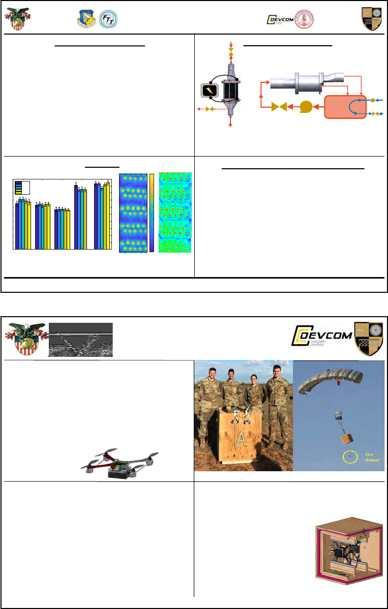
Guidelines for Technical Communication
D/SE and D/CME
United States Military Academy
What: Design a rig to test and analyze
the Advanced Recirculation Total Impingement
Cooling (ARTIC) insert for the Air Force Research
Laboratories (AFRL) to validate computation fluid
dynamics (CFD) models
Why: Increased gas turbine efficiency reduces costs
and environmental impacts. Experiments provide high
quality data.
How: Model the ARTIC insert, maintain similarity to
actual design, conduct Magnetic Resonance
Velocimetry (MRV) and steady-state infrared imaging
(IR) tests
Experimental Setup
Achievements and Future Work
• Both experimental techniques provide robust
datasets that will further inform design
• Little module-to
-module variation
• Proved in-hous
e manufacturing and
experimentation capabilities
• Future Work: Compare to CFD models,
fur
ther combine MRV & IR data, and
investigate film cooling
Results
Figure 4: Nusselt Number vs.
Fluid Velocity Comparison
Project Background
United States Military
Academy at West Point
Department of Civil and
Mechanical Engineering
Turbine Vane Cooling Analysis
Cadets David Bindon, Mattias Cooper, Benjamin Duhaime, and Robert Woodings
Advisors: Dr. David Helmer, CPT Briana Fisk, COL Michael Benson, COL Bret Van Poppel, Dr. Chris Elkins
0
50
100
150
200
250
300
350
Figure 1: Heat Transfer
Schematic
Figure 2: MRV Setup Schematic
0
50
100
150
200
250
300
350
400
450
500
Nusselt Number
Zone 2 Zone 1a Zone 1b Zone 3a Zone 3b
0
50
100
150
200
250
300
350
400
450
500
Module 1
Module 2
Module 3
Module 4
Module 5
Figure 3: Peak Nu in
All Sections
(a) Team Cool Vanes.
Team Hermes
Autonomous Drone Delivery via Airdrop Systems
Nena Riccoboni, Seth Jackson, Ronald Tobin, Abdul Halim Abdul Rahim
Motivation Current capability gap: there is no way to deliver
small, high-value payloads to the soldier from the air with
pinpoint accuracy.
Problem Statement Design and build a scale model system
that carries, dispenses, and initializes multiple Unmanned
Aerial Vehicles (UAVs) from a Joint Precision Airdrop System
(JPADS). Key tasks include:
• Dynamic retasking of small payloads.
• Autonomous release of UAVs to target points.
• Fully autonomous flight of UAVs to target points with
releasable payload bay
FLIGHT TEST RESULTS
SOLDIER PROBLEM / CHALLENGE
DRONE AND DISPENSER DESIGN HIGHLIGHTS
• Autonomous
• Completely unmanned from launch
• Piloted by P
ixhawk and commanded by Raspberry Pi
• Improved Rail System
• Allows drones to drop smoothly
• Any drone fits inside any dispenser
• Detachable Payload
• Released via proximity sensor relay
t
o cargo latch
• Facilitates dynamic retasking
• Environmentally hardened dispenser
• Insulation with heating system
• Door activated by mechanical latch release
• Dispenser: successful test flights under JPADS system
• Survived canopy opening: 100%
success
• Detected location and altitude: 100% success
• Released door: 50% success
• Released dummy drones: 95% success
• Temperature testing
• Drone testing “Throw” and “Mission” modes: 80% success
• Payload release
• Proximity sensor activates cargo latch at 4ft: 100%
success
• Cargo bay survives 4ft drop: 100% success
• Dynamic retasking ability to facilitate change of mission:
validated
Distribution A - Approved for public release; distribution is unlimited.
Drone releases from dispenser during first test.
Team Hermes after a successful test flight.
(b) Team ADDAS.
Figure 5: Example quad charts.
1.01a – 17 August 2020
Page | 35
Guidelines for Technical Communication
D/SE and D/CME
United States Military Academy
A.4 Technical Posters
Many conferences call for participants to create a poster to highlight their work, and some departments at
West Point require cadets to create a poster for their capstone projects on Projects Day. A good poster con-
cisely describes the project, including its motivation, methods, results, conclusions, and recommendations.
Posters should be laid out such that a reader can understand the highlights of your work after a minute of
reading and can fully read the poster after roughly five minutes.
Figure 6 contains a pair of example posters, also produced by cadets during AY2019.
Page | 36
1.01a – 17 August 2020

Guidelines for Technical Communication
D/SE and D/CME
United States Military Academy
Soldier Problem
Soldiers operating in dense urban environments will not be able to
use conventional avenues of approach and means of
reconnaissance due to future enemy capabilities.
Design Challenge
Develop a discrete, safe, and rapidly deployable breaching and
sUAS employment system for DARPA. This system should enhance
SquadX's situational awareness in dense urban environments under
the constraints associated with future enemy sensing and
weaponry.
Theater Study
• Researched wall types in predicted urban environments of
present and future areas of conflict
• Found that the typical wall is precast, non-structural, concrete
panels with Gr. 60 steel rebar (4000-5000 psi)
Concrete Behavior
• American Society of Civil Engineers guidelines used to predict
required forces for generating concrete failure.
• Guided anchor configuration and depth
• Predicted configuration highly accurate with final setup
Quad pod and Net Design
• Analyzed through finite element analysis to ensure success.
• Designed using computer aided design software and then
fabricated in shops
Breach Boys
Team Members: Cadets Aaron Finch, Brandon Shively, Marco Amalfitano, John Kelly, Blake Sandlin, Frank Wu
Sponsors: DARPA, LTC Philip Root, Dr. Scott Fish
Faculty Advisors: LTC Brian Novoselich, CPT Claude Barron, COL Ricardo Morales
Soldier Problem and Design Challenge Solution Design
Testing Results
Design Process
Design Merits
Solution Concept
Concrete is drastically weaker in tension than any other type of
loading. By loading the concrete in shear and tension we can
compromise the wall. Temporary concrete anchors allow a hydraulic
ram to impart force and generate failure. A breach allows UAS
deployment to further squad awareness.
Breach Process
• Drill four strategically spaced holes
• Place temporary concrete anchors in
• Utilize hydraulic ram mounted on
quadpod to generate force until
concrete fails
• Use chisel bit to remove material
• Deploy drone through breach using
sUAS deployment/retrieval device
Components
Figure 4: An example test showing the initial hole spacing, the breach
progress after one iteration and the breach after two iterations
• Generated five successful breaches throughout testing
• Generated a maximum breach size of 7 by 5 inches
• Employed system, from entering area to deploying drone, within 18
minutes
• Total current weight is 87 pounds
• Emissions averaged 1.9 𝑥 10
−5
ppm (PM10) increase during breach
Innovation
Our design presents a novel form of mechanical breaching that
incorporates non-explosive and rapid breaching capabilities for future
“Squad-X.”
Feasibility
• Generates no hazard when operated in enclosed environments
• Generates less noise than current explosive or mechanical
breaching methods
• Breaches more rapidly than current mechanical breaching
methods
• System weight comparable to weight of current mechanical
breaching methods
Technical Strengths
This design has been grounded in ASCE concrete guidelines, finite
element analysis on both the quad-pod and employment-net systems,
mathematical modeling, and thorough testing.
Reduce time on target
• Utilize rotary hammer for removing slack in the system
• Determine most efficient anchor spacing and depth
• Possibly drill additional holes to decrease breach time
Develop multi-use capability
• Utilize anchors for urban rappelling
• Develop systems to breach other obstacles using force of the
hydraulic ram
• Integrate solution with other logistic systems, such as drone
resupply
LTC Philip Root, DARPA
Dr. Scott Fish, UT Austin
COL Christopher Kuhn, Ft Hood, TX
LTC Brian Novoselich
Figure 3: All components for the system. From left to right, rotary
hammer, hydraulic ram and pump, quadpod, temporary concrete
anchors and net design
Figure 2: breaching system
being employed
Acknowledgements
CPT Claude Barron
Mr. Roderick Wilson
Mr. Richard Ellingsen
Mr. William Blackmon
Figure 1: The Breach Boys, breaching kit and two test walls
Decrease System Weight
• Redesigned quadpod featuring lighter
material and a more efficient design
• More compact hydraulic ram
• Lighter Carrying system
Figure 5: Proposed future quadpod
design which will more than half the
current weight.
Future Improvements
(a) Team Breach Boys.
United States Military
Academy at West Point
Department of Civil and
Mechanical Engineering
Cadets David Bindon, Mattias Cooper, Benjamin Duhaime, and Robert Woodings
Advisors: Dr. David Helmer, CPT Briana Fisk, COL Michael Benson, COL Bret Van Poppel, Dr. Chris Elkins
Turbine Vane Cooling Analysis
Experimental Methods and Setup IR Results and Analysis
Magnetic Resonance Velocimetry (MRV)
Problem Statement
To design a rig (or rigs) to test and analyze velocity and heat transfer
characteristics of the Advanced Recirculation Total Impingement Cooling
(ARTIC) turbine vane insert for the Air Force Research Laboratories (AFRL) in
order to validate computational fluid dynamic (CFD) models.
Acknowledgements
Special thanks to Air Force Research Laboratory (AFRL), the Combat
Capabilities Development Command Armaments Center (CCDC AC),
Florida Turbine Technologies Engines Division (FTT), USMA Laboratory
Technicians, and the Richard M. Lucas Center for Imaging at Stanford
University for their funding, support, and assistance.
Steady-State Infrared Imaging (IR)
• Joule-heated, 0.
005” stainless steel
shim models turbine vane inner surface
• Imaged with FLIR A655SC IR camera
• Flow Rate: 408 L
/min (Re=10,000)
• Current and voltage measured
• 45% flow rate through tip bleed
Heat Transfer Rig and IR Camera
• Mapping 2D image to 3D
curve using fiducial marks
• Use characteristic heat
t
ransfer equations to analyze
performance: Nusselt
number and convection
coefficient
• Lowest rate of heat transfer
at jet interaction locations
Distribution A: Approved for public release; distribution is unlimited.
ARTIC Insert MRV Model IR Model
# Modules 23 5 5
Zone 1 (Z1):
X/D, Y/D, Z/D
4.6, 4.6, 3.0 4.6, 4.3, 3.0 4.6, 4.3, 3.0
Zone 2 (Z2):
X/D, Y/D, Z/D
3.9, 3.9, 3.0 4.0, 3.6, 3.0 4.0, 3.6, 3.0
Zone 3 (Z3):
X/D, Y/D, Z/D
9.1, 9.1, 3.0 9.1, 13.1, 3.0 9.1, 13.1, 3.0
# Holes (Z1, Z2, Z3) 30, 17, 9 21, 10, 7 21, 10, 7
Tip Bleed? No Yes Yes
Scale (Insert:Model) 1:1 1:6.67 1:4.67
Design Decisions
Summary of Model Design Decisions
Modeling and Manufacturing Processes
• Modeled stresses, deformation, and flow rate
to achieve desired Reynolds number
• SLA additive manufacturing at CCDC AC
• Material: A
ccura 60 SLA Resin
• Final machining performed at Stanford
MRV
• Modeled theoretical power to achieve
desired ∆T – or temperature difference
• SLA additive manufacturing at USMA
• Material: Form
labs SLA Resin
• USMA water jet cuts copper bus bars.
• Rig sealed with silicone sealant
• Stainless steel shim for HT test spray
pai
nted black to ensure near black
body emissivity
IR
MRV Rig and Supports
Conclusions
Proved in-house manufacturing capabilities
3D velocity field of intricate geometry
Characterized heat transfer performance
2D surface temperature profile
Inform turbomachinery component design
Synthesize MRV & IR data extensively
Investigate phenomenon of film cooling
Analyze high MRV case to validate CFD
Produced IR rig at USMA
MRV techniques employed
IR testing on inner vane surface
MRV & IR Combined
Future Work
From bottom, clockwise: Reservoir setup, MRV rig in
scanner, ARTIC insert produced from MRV data
High Case Low Case
Reynolds Number [ ] 20,000 10,000
Inlet Flow Rate
[L/min]
74.4 37.2
Tip Bleed Flow Rate
[L/min]
33.5 16.7
Resolution [mm] 0.8 0.8
Imaging Matrix Size 222x300x166 222x300x166
Encoded Velocity
[cm/s]
300 (X,Y);
380 (Z)
275 (X,Y,Z)
Total Scans [#] 12 12
Uncertainty ±5% ±5%
Flow and Testing Parameters Table
MRV Results and Analysis
• Robust, high-fidelity, 3D velocity data
• Minimal module-to-module variation
• Two flow cases contain significant differences
• Main feed cavity flow recirculates
• Further analysis can validate CFD
• Informs ARTIC design choices
Feed Cavity Profile,
Flow Moving Left to Right
Recirculation, Inlet Profile Jet-to-Jet Interaction in an Oblique Plane
Example Infrared Image, Zone 1
Temperature Plot [K], Zone 1
Nusselt Number Contour,
Zone 2
MRV Total Velocity,
Zone 2 Impingement Surface
MRV and IR data
show expected
similarity: increased
fluid velocity yields
increased heat
transfer rate!
Main Outlet
Fluid Reservoir 21ºC
Val ve
Cold Fluid
Reservoir
8ºC
Pump
Tip Bleed
Heat
Exchanger
MRV Experimental Setup Diagram
Inlet
Introduction and Motivation
2. Hence, the Advanced Recirculation
Total Impingement Cooling (ARTIC)
gas turbine vane insert to cool the vane.
3. A cooler turbine vane means higher
thermal efficiency, which increases
turbine lifespan, reduces emission
rates, lowers fuel consumption, and
saves money!
4. Fluid dynamics modeling of these
systems must be validated by physical
tests, like Magnetic Resonance
Velocimetry (MRV) or infrared (IR)
imaging.
1. Thermal
efficiency of
turbines
increases when
operating fluid is
at higher
temperatures. A
limiting factor:
vane melting
temperature.
Flow Path through
Forward Insert
Temperature vs. Efficiency for
Varying Gas Turbines
ǂ
ǂ Ibrahim, T. K., Basrawi, F., Rahman, M., 2016. “Optimum Performance Enhancing Strategies of the Gas Turbine Based on the Effective Temperatures”. In MATEC Web of Conferences 2016, p. 01002.
(b) Team Cool Vanes.
Figure 6: Example technical posters.
1.01a – 17 August 2020
Page | 37
Guidelines for Technical Communication
D/SE and D/CME
United States Military Academy
B EXAMPLES
This section contains several examples meant to help you understand the guidance in this document.
B.1 Proofing and Refining
This communication guide was proofread and peer reviewed just as you should do with your own assign-
ments. For example, below are two descriptions of the Communication Model introduced in Section 2.1.
One of these descriptions is identical to the one in that section, while the other is an early draft of the same
information. Notice that the final draft is higher level, develops the explanation more slowly, offers more ex-
amples, and is more in line with the purpose of the paragraph: to introduce readers to the Communication
Model such that they can use it to help them understand the rest of this document.
• Early Draft: Communication begins at the sender, who wishes to impart information to the receiver.
That information exists initially within the sender’s brain as neural connections. To communicate it to
the receiver, the sender must convert the information into something transmittable, a process known
as encoding. Once the information is encoded, it is transmitted as a message using some medium,
called the channel. Along the way, noise interferes with the message. The message is then heard or
seen by the receiver, who decodes it into his or her own brain as neural connections. The receiver
may then reverse the process by providing feedback to the sender, which is also subject to noise.
• Final Draft: When we communicate, our goal is to share information and understand one another.
Say that you want to communicate something to a friend. First, you have to decide how—you might
send a text, use social media, talk over the phone or in person, or even sketch a picture. Whatever
your choice, you have to convert the information from how it exists in your mind into some message
that your friend can sense, usually through vision or hearing. Crafting the message is often the hardest
part of the process, especially when we are restricted in our method of communication. To experience
this yourself, try to explain to someone how to tie their shoes using words only—no pictures, no
demonstrations.
As your friend receives your message, he will try to understand it. Hopefully, you will end up on the
same page, meaning your understanding and your friend’s are close. If they are not, it could be for
a variety of reasons: your words were not clear, Autocorrect mangled your text, your friend could not
hear you, or he did not have some necessary background knowledge. Whatever the outcome, he can
tell you how well he understood you so that you can adjust your message accordingly, although it is
often up to the person sending the message to ask for this feedback.
This process is depicted in Figure 1: a classic model of two-way communication. Although it shows
a conversation between two people, you can extend it to any number of people and any form of
communication.
In this model, you are the sender, who wants to share information with your friend, the receiver.
Your choice of medium—words, a picture, etc.—is called the channel. You convert the information
in your head into a message—a process called encoding—that you communicate along the channel.
Anything that interferes with the message is called noise. Your friend then decodes the message and
forms his own understanding. He might then offer feedback, which is also subject to noise.
Page | 38
1.01a – 17 August 2020
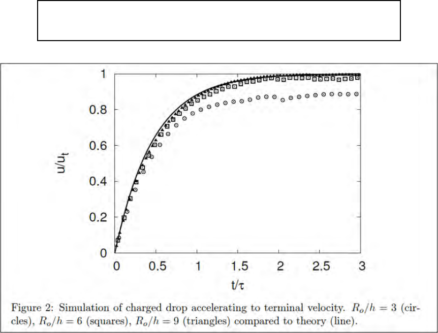
Guidelines for Technical Communication
D/SE and D/CME
United States Military Academy
B.2 Figures and Tables
The following is an example figure with a caption. Note that no legend is used,
but all data sets are described within the caption. This can be an appropriate
technique, depending on the assignment or publication.
Figure 7: Example figure with caption.
1.01a – 17 August 2020
Page | 39

Guidelines for Technical Communication
D/SE and D/CME
United States Military Academy
Here is a more detailed example, illustrating good use of figures and tables in-
tegrated within a section of a technical report. In this example, a stakeholder
has asked for help choosing which house to buy from among six options. The
analysts used value modeling to arrive at a recommendation. Note the figures
and tables, the occasional use of first person, and the description of an equation.
At the stakeholder’s request, we assessed the value of six candidate houses using six metrics: number
of bedrooms, number of bathrooms, lot size, area (square footage) of house, quality of neighborhood, and
whether or not the house had attic storage. The goal of the work was to recommend to the stakeholder the
best house to buy based on the metrics. The six houses are briefly described below using their nicknames,
provided by the stakeholder:
• Commonwealth: A modified 1950’s era ranch house.
• Boo Radley House: A low house in need of a paint job and lawn care.
• Funky Town: A first floor condo in a multi-family home.
• Fixer Downer: An unmodified 1920’s era multi-family home.
• The Burrow: A tall, multi-family home occupied for many years by a single large and reclusive family.
• Lawyer Foyer: A cookie-cutter, newly constructed home, part of a development.
A picture of each house is provided in the appendix.
Table 3 contains the metrics for each house alongside their asking prices. The metric “Neighborhood”
collapses several variables of neighborhood quality into an integer ranging between 1 and 5, with 5 being
best. Variables of neighborhood quality included walkability, crime rate, school ratings, and proximity to
outdoor leisure activity.
Table 3: Metrics and price of each house.
House Bedrooms Bathrooms Lot Size (Acres) Area (ft
2
) Neighborhood Attic Price ($)
Commonwealth 3 2 0.45 1,400 5 No 565,000
Boo Radley 4 2.5 0.75 1,650 3 Yes 515,000
Funky Town 2 1 0.30 850 5 No 550,000
Fixer Downer 3 1.5 0.65 1,200 2 No 375,000
The Burrow 7 3 2.00 2,750 4 Yes 825,000
Lawyer Foyer 5 4 1.75 3,250 3 Yes 850,000
Each house’s metrics were converted to scores ranging between 0 and 100 (with 100 being best) using
the value functions in Figure 8, which reflect the stakeholder’s priorities. Table 4 contains the resulting
scores.
These metric scores were combined into a single overall value for each house using the weighted aver-
age in Equation 2. In this equation, the subscript h corresponds to an individual house and the subscript m
corresponds to an individual metric. Each subscript ranges between 1 and 6—there are six houses and six
metrics. Additionally, v
m
corresponds to the value function for metric m, x
h,m
corresponds to the raw metric
score m for house h, w
m
corresponds to the global weight of metric m, and V
h
corresponds to the total
value of house h. The six global weights and their corresponding swing weights were determined based on
stakeholder preferences and are summarized in Table 5. Note that neighborhood quality has the highest
weight, reflecting the importance of neighborhood quality to the stakeholder.
V
h
=
6
X
m=1
w
m
· v
m
(x
h,m
) for h = 1, ..., 6 (2)
Page | 40
1.01a – 17 August 2020
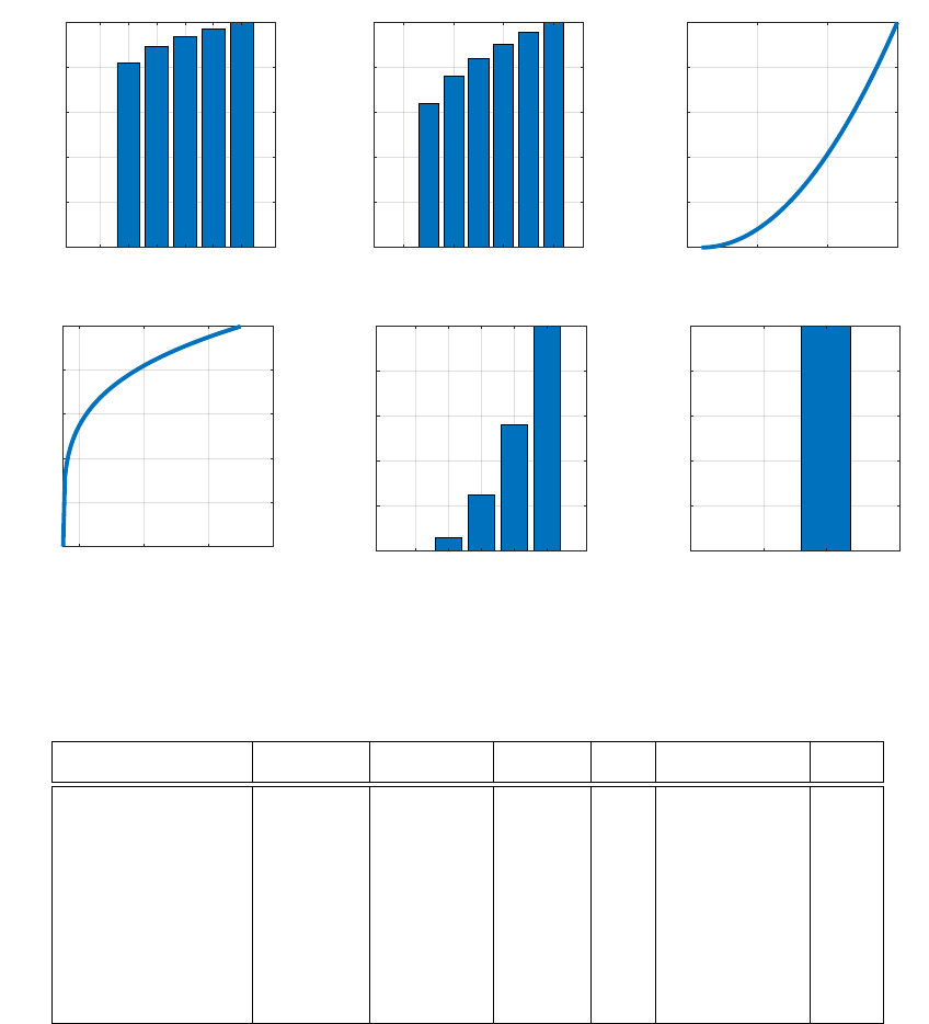
Guidelines for Technical Communication
D/SE and D/CME
United States Military Academy
2 3 4 5 6 7
Bedrooms
0
20
40
60
80
100
Value
1 2 3 4
Bathrooms
0
20
40
60
80
100
Value
0 1 2 3
Lot Size (Acres)
0
20
40
60
80
100
Value
1000 2000 3000 4000
Area (ft
2
)
0
20
40
60
80
100
Value
1 2 3 4 5
Neighborhood
0
20
40
60
80
100
Value
No Yes
Attic
0
20
40
60
80
100
Value
Figure 8: Value functions for the six metrics. Discrete variables are depicted as bars and continuous
variables are depicted as curves.
Table 4: Value scores for each house, corresponding to v
m
(x
h,m
) in Equation 2.
House Bedrooms Bathrooms Lot Size Area Neighborhood Attic
Commonwealth 81.8 83.1 0.8 70.0 100.0 0.0
Boo Radley House 89.2 89.1 4.0 75.8 25.0 100.0
Funky Town 0.0 0.0 0.2 44.7 100.0 0.0
Fixer Downer 81.8 74.4 2.6 63.2 6.3 0.0
The Burrow 100.0 93.5 41.0 92.4 56.3 100.0
Lawyer Foyer 93.8 100.0 30.3 97.7 25.0 100.0
Figure 9 shows the resulting total values (V
h
) for each house and the contributions of each metric to total
value. The figure also contains a “Maximum” case that represents an ideal house where each metric is at
its greatest magnitude.
As shown, Funky Town has the lowest value (31.0) and The Burrow has the highest (76.5). Also note
that while it has the third-highest value (64.9), Commonwealth is in a neighborhood with the highest rating,
unlike the higher-valued The Burrow and Lawyer Foyer.
Figure 10 compares the value of each house to its cost. Notice that Lawyer Foyer and Funky Town are
each dominated, as they cost more yet have less value than other houses (The Burrow and Fixer Downer,
respectively). Also notice the gap in price of more than $250,000 between The Burrow and Lawyer Foyer
and the other four houses.
Based on these results, we plan to recommend The Burrow and Commonwealth to the stakeholders for
further discussion. The Burrow was selected because it has the highest value, and Commonwealth was
selected for its relatively high value, low price compared to The Burrow, and its high-quality neighborhood.
1.01a – 17 August 2020
Page | 41
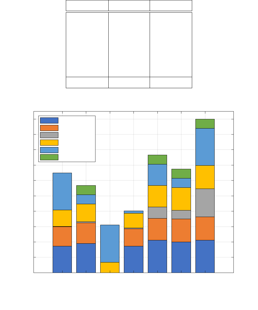
Guidelines for Technical Communication
D/SE and D/CME
United States Military Academy
Table 5: Metric weights.
Metric Swing Weight Global Weight
Bedrooms 175 0.212
Bathrooms 125 0.152
Lot Size 150 0.182
Area 125 0.152
Neighborhood 200 0.242
Attic 50 0.061
Sum 825 1.000
64.9
56.8
31.0
40.2
76.5
67.5
100.0
Commonwealth
Boo Radley
Funky Town
Fixer Downer
The Burrow
Lawyer Foyer
Maximum
0
10
20
30
40
50
60
70
80
90
100
Total Value (V
h
)
Bedrooms
Bathrooms
Lot Size
Area
Neighborhood
Attic
Figure 9: Stacked total values of each house.
Page | 42
1.01a – 17 August 2020
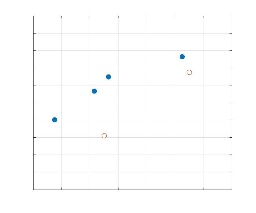
Guidelines for Technical Communication
D/SE and D/CME
United States Military Academy
300 400 500 600 700 800 900 1000
House Cost (Thousands of Dollars)
0
10
20
30
40
50
60
70
80
90
100
Total Value (V
h
)
House Value versus Cost
Commonwealth
Boo Radley
House
Funky Town
Fixer Downer
The Burrow
Lawyer
Foyer
Figure 10: House values versus cost. Open circles represent dominated houses.
1.01a – 17 August 2020
Page | 43

Guidelines for Technical Communication
D/SE and D/CME
United States Military Academy
B.3 Equations
This example shows how to develop a series of equations in a paper. The
premise is that the analysts have been asked to estimate the flight time of a fired
projectile. They use a simple model to calculate the projectile’s trajectory and
arrive at an estimated time. Note how each variable is introduced and defined
and how the equations are read and punctuated as part of the text.
To estimate the flight time of the projectile, we modeled it without air resistance and assuming flat terrain.
Its vertical position as a function of time is represented by Equation 3,
p(t) = p
0
+ v
0
t +
1
2
gt
2
, (3)
where t represents time, p(t) represents the vertical position of the projectile at time t, p
0
represents its
initial vertical position, v
0
its initial vertical velocity, and g the local gravitational acceleration constant, ap-
proximated as 32.2 ft/s
2
.
The flight time can be estimated by solving for t when p(t) is equal to 0:
0 = p
0
+ v
0
t +
1
2
gt
2
. (4)
Because the projectile starts on the ground and we are modeling flat terrain, its initial position p
0
is also
0, yielding
0 = v
0
t +
1
2
gt
2
, (5)
which simplifies to
0 = t(v
0
+
1
2
gt). (6)
Equation 6 has two solutions for t: t = 0, which is the start of the projectile’s flight; and
t =
−2v
0
g
. (7)
For a projectile launched with a vertical velocity at 150 ft/s (approximately 102 mph), the flight time in
seconds would be calculated as
t =
−300
−32.2
≈ 9.3. (8)
Notice that the answer is shown to only one significant digit. This is appropriate
for the assumptions of the problem. The calculator answer of 9.31677019 is far
too precise and would make no sense to report. Refer to the SLAM for a refresher
on numerical precision and measurement reporting (a link is in Appendix C).
Page | 44
1.01a – 17 August 2020

Guidelines for Technical Communication
D/SE and D/CME
United States Military Academy
B.4 Example Theory or Methods Section
This example extends the previous example and illustrates a full section of a
report that could be titled Methods, Mathematical Modeling, or Theory. Note
the multi-line equation, which is not numbered because it is used primarily for
clarification. Also note the placement of references for some equations.
For internal flow through a tube of circular cross section, the Reynolds number can used to classify the
flow regime as laminar, turbulent, or within the transition region, as [Bergman, Ch. 8]
Re
D
=
ρu
m
D
µ
=
4 ˙m
πDµ
(9)
with the following ranges for flow regime
2, 300 ≤ Re
D
Laminar
2, 300 < Re
D
< 10, 000 Transition
10, 000 ≥ Re
D
Turbulent,
where u
m
is the mean flow velocity, formally defined in the Bergman text as
u
m
=
2
r
2
o
Z
r
o
0
u(r, x)rdr (10)
with r
o
the inner radius of the tube. Common assumptions—incompressible flow, constant fluid properties,
and laminar fully developed flow—further simplify the mathematical model to Poiseuille flow, with a mean
flow velocity expressed as [Bergman, Ch 8]
u
m
= −
r
2
o
8µ
dp
dx
, (11)
with
dp
dx
the axial pressure gradient. The experimental apparatus is capable of generating flows with
Reynolds numbers near 5,000, short of the fully-turbulent regime. For this reason, observations remain
within the laminar flow regime for the laboratory.
As expected, thermal considerations of the internal convection problem begin with a first-law energy
balance for a control volume, expressed as
q = ˙mc
p
(T
m,o
− T
m,i
), (12)
where T
m,i
and T
m,o
represent the mean temperatures at the tube inlet and outlet, respectively, and c
p
the
specific heat. The mean temperature is defined in Bergman and other texts as
T
m
=
2
u
m
r
2
o
Z
r
o
0
uT rdr. (13)
Most convection heat transfer problems require computation of the Nusselt number,
Nu
D
= f(Re
D
, Pr) =
hD
k
f
, (14)
where k
f
represents the thermal conductivity of the fluid and h the convection coefficient. For correct
computation of both relevant non-dimensional parameters, Re
D
and Nu
D
, the most appropriate thermo-
physical properties must be retrieved from appropriate table references. Bergman derives an expression
for the axial variation of the mean temperature, T
m
using a control volume approach, as
dT
m
dx
=
q
00
s
P
˙mc
p
=
P
˙mc
p
h(T
s
− T
m
), (15)
1.01a – 17 August 2020
Page | 45

Guidelines for Technical Communication
D/SE and D/CME
United States Military Academy
where q
00
s
represents the surface heat flux, ˙m the mass flow rate, P the perimeter (equal to πD for tubes of
circular cross section), and T
s
the surface temperature. The constant surface temperature case is approxi-
mated with the ice bath, so the analytic solution of Equation 15 becomes [Bergman, Ch 8]
∆T
o
∆T
i
=
T
s
− T
m,o
T
s
− T
m,i
= exp
−
P L
˙mc
p
¯
h
!
, (16)
with
¯
h the average convection coefficient over the full tube length.
An alternative form of the Equation 16 employs the overall heat transfer coefficient,
¯
U, in place of
¯
h to
account for the conduction through tube,
∆T
o
∆T
i
=
T
∞
− T
m,o
T
∞
− T
m,i
= exp
−
¯
UA
s
˙mc
p
!
, (17)
where T
∞
replaces T
s
and represents the ice bath temperature, and A
s
is the tube’s surface area. Equa-
tion 17 can be used to express the rate of heat transfer, and taking the form of resistance in a thermal circuit
(electricity analog) with R as the thermal resistance yields
1
UA
s
= R
tot
= R
conv ection
+ R
conduction
=
1
h
i
A
s,i
+
ln(D
o
/D
i
)
2πkL
, (18)
where D
o
and D
i
represent the outer and inner diameters, respectively, and L the tube length.
For laminar, fully developed flow and constant surface temperature conditions, the Nusselt number for a
tube of circular cross section can be approximated as
Nu
D
= 3.66. (19)
Combining Equations 14 and 16, measured data is used to solve for the modeled tube length, L, which
is then compared to the actual tube length. The analysis can be repeated using Equation 17 in lieu of
Equation 16 to reveal the effects of conduction through the tube wall, as shown by Equation 18.
Page | 46
1.01a – 17 August 2020

Guidelines for Technical Communication
D/SE and D/CME
United States Military Academy
B.5 Department of Defense Distribution Statements
Distribution statements provide guidance for UNCLASSIFIED documents be-
yond the provisions of security classification. Many technical projects require
distribution statements on some or all documents, and all posters and presenta-
tions must be marked with the appropriate distribution statements for final pre-
sentation at Projects Day.
The following distribution statements and notices are authorized for use on DoD technical documents.
Additional information for each distribution statement can be found at the Defense Technical Information
Center (DTIC, www.dtic.mil).
• DISTRIBUTION A. Approved for public release: distribution unlimited.
• DISTRIBUTION B. Distribution authorized to U.S. Government Agencies (reason) (date of determina-
tion). Other requests for this document shall be referred to (controlling DoD office).
• DISTRIBUTION C. Distribution authorized to U.S. Government Agencies and their contractors (rea-
son) (date of determination). Other requests for this document shall be referred to (controlling DoD
office).
• DISTRIBUTION D. Distribution authorized to Department of Defense and U.S. DoD contractors only
(reason) (date of determination). Other requests for this document shall be referred to (controlling
DoD office).
• DISTRIBUTION E. Distribution authorized to DoD components only (reason) (date of determination).
Other requests for this document shall be referred to (controlling DoD office).
• DISTRIBUTION F. Further dissemination only as directed by (controlling office) (date of determination)
or higher DoD authority.
1.01a – 17 August 2020
Page | 47
Guidelines for Technical Communication
D/SE and D/CME
United States Military Academy
C RESOURCES
• LaTeX: Learning LaTeX takes time and assistance from experienced users. A great place to start
is Overleaf.com, which offers an introduction to LaTeX and a collaborative space to create LaTeX
documents. See https://www.overleaf.com/.
• R Markdown: An introduction to R Markdown is available at https://rmarkdown.rstudio.com/.
• U.S. Army Regulations: U.S. Army Regulation 25-50, Preparing and Managing Correspondence, is
available at https://armypubs.army.mil/epubs/DR_pubs/DR_a/pdf/web/r25_50.pdf.
• Science Laboratory Analysis Manual (SLAM): A link to the full SLAM is available here:
https://usarmywestpoint.sharepoint.com/sites/setcfeedback.
• West Point Writing Program: Figure 11 shows the high-level components of the WPWP (Figure 11a)
and the strategies it uses to help cadets improve their writing (Figure 11b). You can find more infor-
mation about the WPWP here:
https://westpoint.edu/academics/curriculum/west-point-writing-program.
Page | 48
1.01a – 17 August 2020
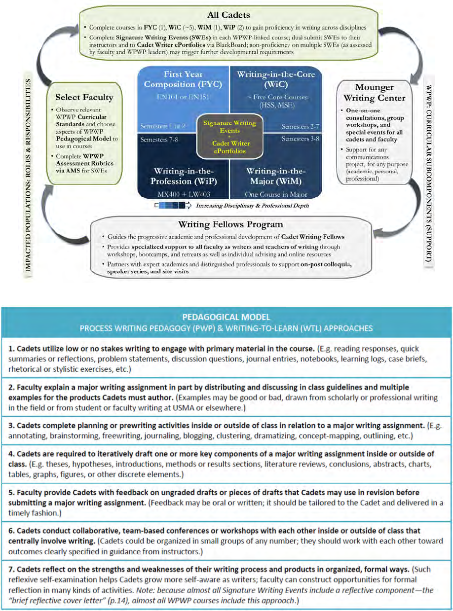
Guidelines for Technical Communication
D/SE and D/CME
United States Military Academy
(a) Major components.
(b) Pedagogical model.
Figure 11: Components and pedagogical model of the WPWP.
1.01a – 17 August 2020
Page | 49
Guidelines for Technical Communication
D/SE and D/CME
United States Military Academy
D CHECKLIST
For All Assignments
2 Correct format used, including:
2 Page/slide numbers
2 Document/slide template
2 Margins
2 Headers and footers
2 Font face and size
2 Citations
2 Cover sheet
2 Brown bomber, including name plates
2 Specific requirements of assignment
2 Assignment:
2 Tailored to audience
2 Purpose driven
2 Peer reviewed
2 Assignment proofed for:
2 Spelling
2 Punctuation, syntax, capitalization
2 Consistency in style
2 Brevity and clarity
2 Use of numbers instead of words
2 Appropriate significant digits
2 Appropriate math symbols (e.g., ≥, not
>=)
2 Introduction covers:
2 Background
2 Motivation
2 Purpose
2 Scope
2 Literature Review (if appropriate)
2 Conclusion:
2 Reintroduces key points
2 Does not introduce new technical
information
2 Figures and tables aesthetically pleasing, easy
to read
For Papers
2 Figures and tables referenced, labeled,
captioned
2 Equations labeled (where appropriate)
2 Use of first person, passive voice, and
nominalization appropriate
2 One font used (exceptions: code, math, some
quotes)
For Presentations
2 Main text font size between 14 and 20
2 White background used
2 Colors easy to distinguish on projector
2 Title slide includes:
2 Name(s) of presenter(s)
2 Date
2 Venue (if appropriate)
2 Title addressing purpose of presentation,
not name of assignment
2 Graphic (if appropriate)
2 Critical slides included:
2 Summary
2 Agenda/Outline
2 “Thank you! Any questions?”
2 Audience regularly reminded of agenda
2 Contact information present
2 Backup slides are high quality
2 Relevant graphics included
2 Image sources written on respective slides
2 Figures and tables annotated appropriately
2 Rehearsals conducted
2 Slides printed
2 Slides emailed (for teleconferences)
2 Slides contain bumpers, where appropriate
2 For group presentations, all group members:
2 Aware of their slides to present
2 Prepared to present
2 Backup plan established for technological or
personnel problems
Page | 50
1.01a – 17 August 2020
Guidelines for Technical Communication
D/SE and D/CME
United States Military Academy
E CITATIONS
1. Society for Technical Communication, n.d.
2. Parnell, Driscoll, & Henderson, 2011, p. 3
3. Strunk & White, 2000, p. 23
4. Omega Alpha Association, n.d.
5. Pinker, 2014, p. 59
6. R Markdown, n.d.
7. Paraphrased from Weissberg & Baker, 1990, p. 41
8. Paraphrased and simplified slightly from Alred, Bruslaw, & Oliu, 2012, pp. 521–523
9. Inspired by a similar example in Pinker, 2014, p. 55
10. Memmott, 2013
11. Sword, 2012
12. This discussion is modified slightly from Alfred, Brusaw, & Oliu, 2012, p. 364
13. Alred, Brusaw, & Oliu, 2012, p. 395
14. Merriam-Webster, n.d.
15. Adapted from Pinker, 2014, p. 54
16. Modified slightly from Pinker, 2014, p. 45
17. Adapted from Alred, Brusaw, & Oliu, 2012, p. 576
18. Figure 2a from Bridgham, Henderson, & Li, 2019
19. National Eye Institute, n.d.
20. This suggestion is based on presentations given by CDTs J.M. Borrego Acosta, A. Henderson, and S.
Rosdahl in AY19-2 of SE302.
21. Figure 4 modified from Carroll, Cromer, & Franco, 2019
22. Inspired by presentations given by CDT J. Tweedy during AY19-2 of SE302
23. Some of the guidance in this section was based on Alred, Bruslaw, & Oliu, 2012, pp. 164–169
24. Sehgal, 2016
1.01a – 17 August 2020
Page | 51
Guidelines for Technical Communication
D/SE and D/CME
United States Military Academy
25. Alred, Brusaw, & Oliu, 2012, p. 184
26. Guidance based on Finkelstein, 2005, pp. 215–216
27. U.S. Army, 2013
Page | 52
1.01a – 17 August 2020
Guidelines for Technical Communication
D/SE and D/CME
United States Military Academy
F REFERENCES
1. Alred, G.J., Brusaw, C.T., and Oliu, W.E. (2012). Handbook of Technical Writing: Tenth Edition.
Boston, MA: Bedford/St.Martins.
2. Bridgham, W., Henderson, S., and Li, E. (2019). Detailed design review. Final project for SE302
during AY19-2.
3. Carroll, M., Cromer, S., and Franco, D. (2019). Detailed design review. Final project for SE302 during
AY19-2.
4. Communication. (n.d.). Merriam-Webster Online; Retrieved June 7, 2019, from https://www.merriam-
webster.com/dictionary/communication
5. Finkelstein, L., Jr. (2005). Pocket book of technical writing for engineers and scientists (2nd ed.).
New York, NY: McGraw-Hill.
6. Memmott, M. (2013). It’s true: ‘mistakes were made’ is the king of non-apologies; Retrieved June 10, 2019,
from https://www.npr.org/
7. Merriam-Webster. (n.d.). Singular ‘they’; Retrieved June 11, 2019, from
https://www.merriam-webster.com/words-at-play/singular-nonbinary-they
8. National Eye Institute. (n.d.). Facts about color blindness; Retrieved June 21, 2019,
from https://nei.nih.gov/health/color_blindness/facts_about
9. Omega Alpha Association. (n.d.); Retrieved June 17, 2019, from https://omegalpha.org/
10. Parnell, G., Driscoll, P., and Henderson, D. (2011). Decision making in systems engineering and
management (2nd ed.). Hoboken, NJ: John Wiley and Sons.
11. Pinker, S. (2014). The sense of style: the thinking person’s guide to writing in the 21st century.
New York, NY: Viking.
12. R Markdown. (n.d.). R Studio; Retrieved June 7 2019, from https://rmarkdown.rstudio.com/
13. Sehgal, K. (2016). How to write emails with military precision; Retrieved November 23, 2019, from
https://hbr.org/2016/11/how-to-write-email-with-military-precision
14. Society for Technical Communication. (n.d.). Defining technical communication. Retrieved June 10, 2019,
from https://www.stc.org/about-stc/defining-technical-communication/
15. Strunk, W., Jr., and White, E.B. (2000). The elements of style. Needham Heights, MA: Longman.
16. Sword, H. (2012) Zombie Nouns; Retrieved November 24, 2019, from
https://opinionator.blogs.nytimes.com/2012/07/23/zombie-nouns/
17. U.S. Army. (n.d.). Army Uniforms; Retrieved June 7, 2019, from https://www.army.mil/uniforms/
18. U.S. Army. (2013). Army Regulation 25-50: Preparing and Managing Correspondence. Retrieved
June 7, 2019, from https://armypubs.army.mil/epubs/DR_pubs/DR_a/pdf/web/r25_50.pdf
19. Weissberg, R. and Buker, S. (1990). Writing up research: experimental research report writing for
students of English. Englewood Cliffs, NJ: Prentice Hall Regents.
1.01a – 17 August 2020
Page | 53
